ADS-B
The Course 16 crossover lab
Please Log In for full access to the web site.
Note that this link will take you to an external site (https://shimmer.mit.edu) to authenticate, and then you will be redirected back to this page.
Background and Goals
Airplanes are large metal sky tubes that fly. Investigations as to why this happens are ongoing, but one thing we definitely know is that it's Bad if more than one plane is in the same place at the same time. For that reason, planes regularly broadcast Automatic Dependent Surveillance-Broadcast (ADS-B) packets describing their position, velocity, altitude, and identifying information using radio waves.
This lab will use the RFSoC to receive, demodulate, and decode ADS-B packets (technically called "squitters") from real planes in the local area using an antenna and LNA in the lab. Since many of you will likely choose to implement existing RF modulations and protocols for your final projects, this lab will take you through the process of figuring out how to do that using a combination of the RFSoC PL and PS, starting at the raw radio waves coming into your ADC and ending with actual latitude/longitude coordinates of airplanes.
This lab is mainly based on these articles, which may be useful to read for background:
- Exploit.org Article on Decoding ADS-B using Software-Defined Radios (SDRs)
- MathWorks Article on Using an FPGA and MATLAB to Decode ADS-B
How ADS-B Works
Wireless protocols are like onions: they have layers. The bottom layer is the physical layer--how the information is actually sent through the air. To decode a new wireless protocol, we start by researching the two most important parameters of the physical layer: frequency and modulation. ADS-B uses a 1090 MHz carrier frequency. Its modulation is on-off keying with Manchester coding. Commercial FM from last week was similar, except that it was modulating the frequency instead of the amplitude. There was a "baseband signal" that was created that was itself comprised of not only audio, but variations of audio, pilot signals, digital signals, etc... which are all wrapped up and then modulated with FM. All wireless communication works on this principle of modulating "baseband" information onto a higher-frequency carrier. In general, the more modern the protocol, the more complicated (and potentially numerous) the layers are, but this is also what enables more modern protocols to be so "good" in terms of fidelity and robustness. Consider that ADS-B sends data unreliably at about 1 million bits per second using fairly powerful (250 Watts!) transmitters. Modern Wi-Fi sends data reliably at 6.8 billion bits per second using pretty weak transmitters (64 milliwatts, albeit over much shorter distances).
The On-off keying in ADS-B is a special case of amplitude modulation where the amplitude is either high or low (recall that amplitude modulation uses the amplitude of the sine wave to convey information). So if we decided that each bit of a digital message was 1000 samples long and sent the message "1011", then it would ideally look something like this:
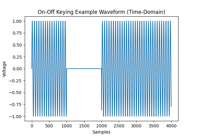
For historical reasons that date all the way back to the first IFF systems, ADS-B uses a 0.5 microsecond bit period, so each bit lasts 0.5 microseconds (how many samples this is depends on your sample rate).
You might notice that, in this simple scheme, a long string of zeroes would look the same as no signal at all. To get around this, ADS-B uses Manchester coding (also called pulse-position modulation or PPM), which encodes every bit as two bits. A 1 is encoded as "10", and a 0 is encoded as "01". So "1011" becomes "10011010". This is like a simpler form of the 8b/10b encoding you encountered in 6.2050.

Another problem that might become immediately apparent to those of you who remember writing the UART controller in 6.2050 is the problem of synchronization. Much like UART, ADS-B has no clock signal, only data, so we need to be able to know exactly when the message started in order to sample the bits at the right time. So ADS-B messages always start with a recognizable high-low-high-low-low-low-low-high-low-high-low-low-low-low-low-low preamble sequence:
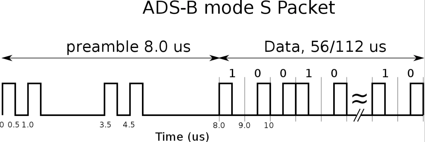
The Manchester-coded data usually lasts 112 microseconds. Since the bit period is 0.5 microseconds but we send 2 physical bits per bit of actual data, that means we can send 112 bits of actual data encoded as 224 ones and zeroes.
The next layer of this protocol tells us how the bits actually correspond to information. In the case of ADS-B, the first 5 data bits are the "downlink format" and should always be 17. The next 3 bits are "transponder capability," which informs systems that query the planes like air traffic control towers what information the ADS-B transponder is capable of giving.
The next 24 bits are the ICAO number, which uniquely identifies the airplane. You can usually search these up in hex online via the globe.adsbexchange.com website to find the owner of a plane (except for some special planes where the owner changes the number to evade tracking). For example, 0xA7FAAD is a 2005 Airbus A-320 plane registered to JetBlue with callsign JBU1852 (as of Oct. 26, 2025--the ICAO numbers are usually fixed, but commercial callsigns change based on what flight the plane is on).
The next 56 bits encode the plane's position, velocity, altitude, etc. Since that is too much data to send in 56 bits, there are a few possible formats for these bits depending on what information is being sent.
The last 24 bits are a Cyclic Redundancy Check (CRC) of the preceding 88 bits to ensure that the message is not corrupted.
I/Q Mixing Concepts
This part is confusing, but I assure you that understanding it now will make your final projects much easier.
Knowing that ADS-B uses on-off (amplitude) modulation suggests that the first stage in our decoder will be determining the amplitude of the incoming signal. Recall that the incoming signal is a stream of complex numbers I + jQ representing the in-phase ( I ) and quadrature ( Q ) signals.
The numerically controlled oscillator (NCO) for the RF-ADC's mixer will be set to the negative of the ADS-B carrier frequency, so -1090 MHz. Theoretically, the real signal of voltages going into the ADC modulated by a time-varying amplitude A(t) can be written as:
Where \omega_{\text{carrier}} = 2 \pi (1090 \,\, \mathrm{MHz}) .
The RF-ADC's IQ mixer mixes (multiplies) V(t) with a complex signal NCO(t) = e^{-j \omega_{\text{nco}} t} where \omega_{\text{nco}} = 2 \pi (1090 \,\, \mathrm{MHz}) too, so the output should ideally be:
Which Euler tells us should be:
In the case where \omega_{\text{carrier}} = \omega_{\text{nco}} , this becomes:
Recall that the IQ mixer has lowpass filters after the mixers:
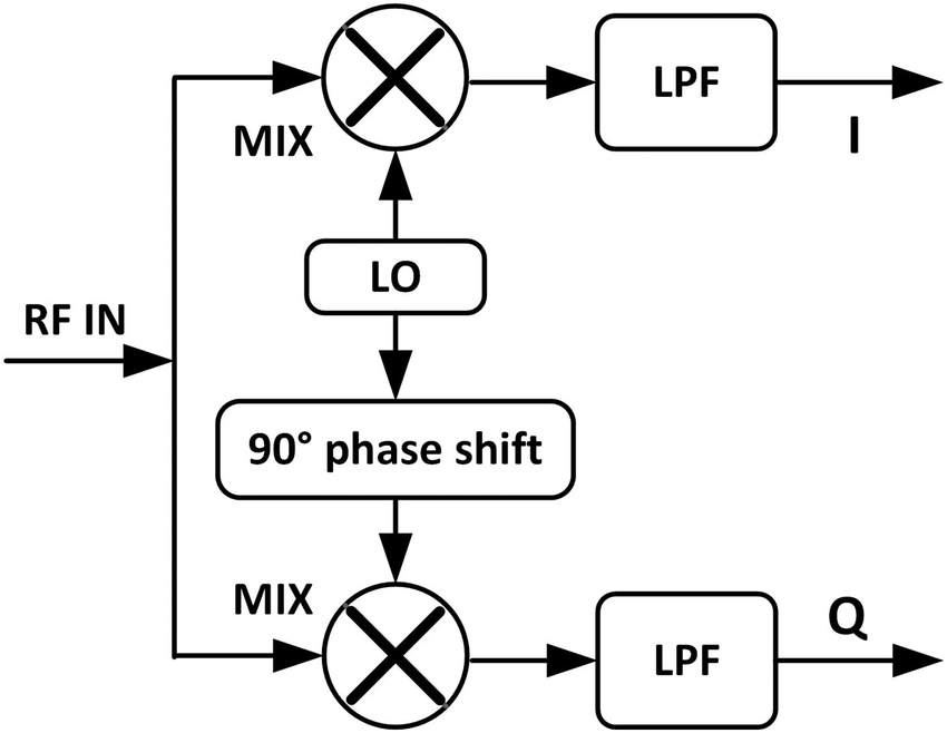
The lowpass filters kill the annoying 2 \omega terms, leaving us with the very nice:
That's great! So to get the amplitude of our signal, we just set the NCO to -1090 MHz and take only the real/I/in-phase channel coming out of the RF-ADC. The I/Q vector lies along the real axis and just varies in length over time, corresponding to A(t) . Very easy. This makes intuitive sense because we know that mixing adds frequencies, so adding 1090 MHz to -1090 MHz gets us 0 Hz; we have "mixed the signal down to baseband."
Unfortunately, hardware is called hardware because it is hard. It turns out that this only works if the incoming signal is at exactly the right frequency. If, for example, \omega_{\text{carrier}} = 2 \pi (1090 \,\, \mathrm{MHz} + 1 \,\, \mathrm{Hz}) , then we have:
That's annoying, now instead of being a purely real vector varying only in length, the I/Q vector is spinning at 1 Hz. We can't look at just I or just Q to get the magnitude because the vector is spinning.
It also turns out that if the phase of the incoming signal is wrong relative to the NCO, the simple method will have issues. If the incoming signal were shifted 90 degrees, then we would see zero I and only Q would vary with A(t) .
To understand this intuitively is a bit tricky, so I made this interactive visualization that lets you play around with the concept of I/Q demodulation of an AM signal:
0 rad
10 Hz
Play around with the above visualization. Try changing the carrier frequency slowly--what happens to the "IQ data" waveform as the carrier and NCO frequency become separated? Now try setting both carrier and NCO back to the same value, but slowly change "NCO phase." How does this affect I and Q?
Building the Decoder
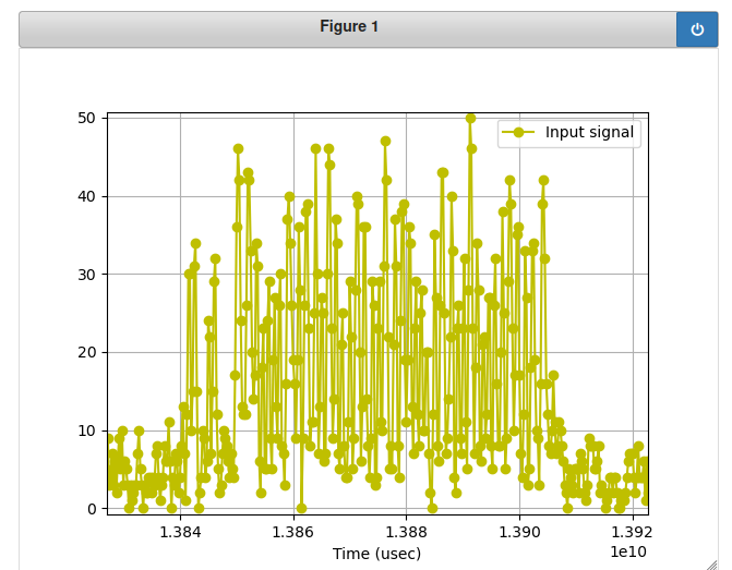
Due to the aforementioned issues with mixing, the first step in decoding should probably be to take the magnitude of the signal \sqrt{I^2 + Q^2} . Indeed, the first version of this lab that I wrote began with using our CORDIC to take the magnitude of the I/Q vector. However, the rest of our 64 MHz of captured bandwidth (I/Q sampling is effectively 2 samples per timestep, so 64 MSps is 64 MHz of captured bandwidth despite Nyquist saying it should be 32 MHz of captured bandwidth) contains various other noise and interfering signals in the real world:
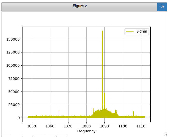
Just taking the magnitude of the raw I/Q signal adds all the noise and other signals within our capture bandwidth into our magnitude signal, swamping the weaker ADS-B packets. For that reason, we actually start by filtering the I/Q data. ADS-B is nominally a 2 MHz wide signal, but it's a square wave, so a bit more bandwidth represents it better. I generated a lowpass FIR filter with the following settings and set the coefficients to be 8-bit integers for our AXIS FIR:
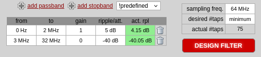
The slow rolloff over a MHz makes the filter take up fewer taps, which will use fewer resources on the FPGA. The 75 coefficients ended up being:
lowpass_coeffs = [1, 0, 0, 0, 0, 0, 0, 0, -1, -1, -1, -1, -2, -2, -2, -2, -2, -2, -2, -2, -2, -1, -1, 0, 0, 1, 2, 3, 4, 5, 6, 7, 7, 8, 9, 9, 9, 9, 9, 9, 9, 8, 7, 7, 6, 5, 4, 3, 2, 1, 0, 0, -1, -1, -2, -2, -2, -2, -2, -2, -2, -2, -2, -1, -1, -1, -1, 0, 0, 0, 0, 0, 0, 0, 1] # 2 MHz passband, 3 MHz stopband
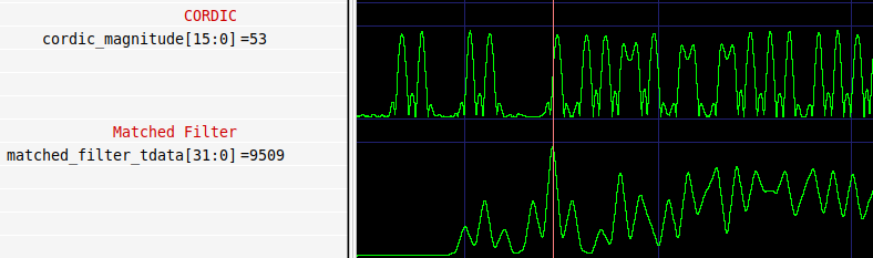
We apply this filter separately to the I and Q data streams before putting them into the CORDIC to calculate the magnitude. What comes out of the CORDIC will be a stream of magnitude data that looks like our ADS-B signal:
As we mentioned before, locking onto the preamble sequence is critical to a successful decode. Much like UART in 6.2050, if you sample the data misaligned in time, you get a garbage decode.
The signal will contain noise and may vary in amplitude, so we're not looking for a exact waveform, but rather any waveform that follows the preamble's shape. One of the most powerful DSP tools for looking for a certain shape in a signal is matched filtering.
A matched filter contains a recording of the waveform it's looking for. It slides this waveform along the incoming data, taking its dot product with the signal at each position. Sound familiar? Yes, this is the exact same thing as the convolution done by the FIR filter (ok, technically, this is correlation, not convolution, but if you are deep enough into DSP to know that you don't need this explanation).
"Technically correct is the best kind of correct; technically, it's the only kind of correct." -- wise RF engineer
The output of the matched filter will peak when its input data is perfectly aligned with the preamble sequence:
How can we reliably detect this peak? I initially tried a simple threshold, but found that it tended to trigger early for strong signals (which have numerically larger correlations). Triggering early would cause misaligned sampling of the digital data and garbage output.
I then realized that we needed to detect the peak itself. I wrote a "local maximum" detector, which simply detects whenever a sample from the correlation signal is greater than both the sample before and the sample after. I combined this with a fixed threshold that I determined empirically. This provides an ok solution for detecting when the preamble has just occurred. A better solution would probably use a long moving average of the last N samples and determine a threshold that way.
// Detects when we see a local maximum (x[i-1] < x && x[i+1] < x) that is greater than the threshold.
module preamble_detector #
	(
		parameter integer C_S00_AXIS_TDATA_WIDTH	= 32,
		parameter integer C_M00_AXIS_TDATA_WIDTH	= 32
	)
	(
		// Ports of Axi Slave Bus Interface S00_AXIS
		input wire  s00_axis_aclk, s00_axis_aresetn,
		input wire  s00_axis_tlast, s00_axis_tvalid,
		input wire [C_S00_AXIS_TDATA_WIDTH-1 : 0] s00_axis_tdata,
		input wire [(C_S00_AXIS_TDATA_WIDTH/8)-1: 0] s00_axis_tstrb,
		output logic  s00_axis_tready,

        input wire [C_S00_AXIS_TDATA_WIDTH - 1:0] preamble_detector_threshold,
        output wire trigger
	);

    assign s00_axis_tready = 1'b1;

    logic [C_S00_AXIS_TDATA_WIDTH - 1: 0] lookback_window [2:0];

    logic local_maximum;
    assign local_maximum = lookback_window[1] > lookback_window[0] && lookback_window[1] > lookback_window[2];
    assign trigger = local_maximum && lookback_window[1] >= preamble_detector_threshold;

    always_ff @(posedge s00_axis_aclk) begin
        if (~s00_axis_aresetn) begin
            for (integer i = 0; i < 2; i = i + 1) begin
                lookback_window[i] <= 0;
            end
        end
        else begin
            if (s00_axis_tvalid) begin
                // Add data to the lookback pipeline that determines local maxima.
                lookback_window[0] <= s00_axis_tdata;
                lookback_window[1] <= lookback_window[0];
                lookback_window[2] <= lookback_window[1];
            end
        end
    end

endmodule
Once a local maximum greater than the threshold is detected, the above module fires off a trigger signal, which will tell the ADS-B decoder to start decoding. This is similar to how the falling edge of CS tells your SPI controller to start decoding, or how the start bit tells the UART controller to start decoding.
The ADS-B decoder will apply a fixed threshold to the magnitude signal to make it digital, then sample each bit in the middle of each bit period. You can implement it with an FSM and some counters.
Some important notes:
-
The ADS-B data bits come in most-significant-bit (MSB) first (as is common for most communications things). So
6'b10_01_01decodes to3'b100, not3'b011. -
A 0.5 microsecond "physical bit" (which makes up half of a 1 microsecond bit of data) is 32 samples at 64 MSps.
-
The trigger signal will go high around the end of the preamble, so the first time you sample the data should actually be around 32/2 = 16 clock cycles after seeing the trigger. Since the local max detector introduces some delay, the first time you sample should be about 13 clock cycles after seeing trigger. After that, you wait 32 samples for the next sampling point as usual.
-
The trigger signal may go high again during the squitter, you should ignore this. Once the FSM has been triggered, it should keep running for 112 data bits no matter what.
-
"00" and "11" are invalid in Manchester coding. In testbenching, it's helpful to put an X into your output data when you see these so you can quickly see if something is going wrong. In the real world, just treat them as zero data bits (or you could have some super fancy algorithm that uses the CRC of the ADS-B squitter to figure out what the missing bits were supposed to be, but we don't have time for that).
-
We are ignoring the ready signal from downstream since our downstream will be a big FIFO that should hopefully not fill up. If an ADS-B squitter is lost, so be it. Just set valid high for one clock (no more!) when your data is done.

Due to time and sanity constraints, we have provided all of the code for you for the CORDIC, the local maximum detector, the FIRs, the top-level module that connects them all together, as well as a Cocotb testbench that streams real recorded ADC data of ADS-B squitters into your top-level to check that everything is working. All you need to write is the FSM in hdl/adsb_decoder.sv that takes in a trigger signal and magnitude data to produce 112-bit ADS-B squitters over AXI.
The testbench will run your decoder against actual I/Q data and check that its output is correct. If you decode some bogus squitters at the start that cause the test to fail, it's fine as long as you decode the two actual squitters correctly. Unfortunately, Surfer does not yet support plotting in "analog mode," which is tremendously useful for DSP things where you want to see the shape of signals rather than their numerical values. GTKWave supports this. If you cannot run GTKWave on your computer, it runs on the lab computers. A good simulation should look something like this:
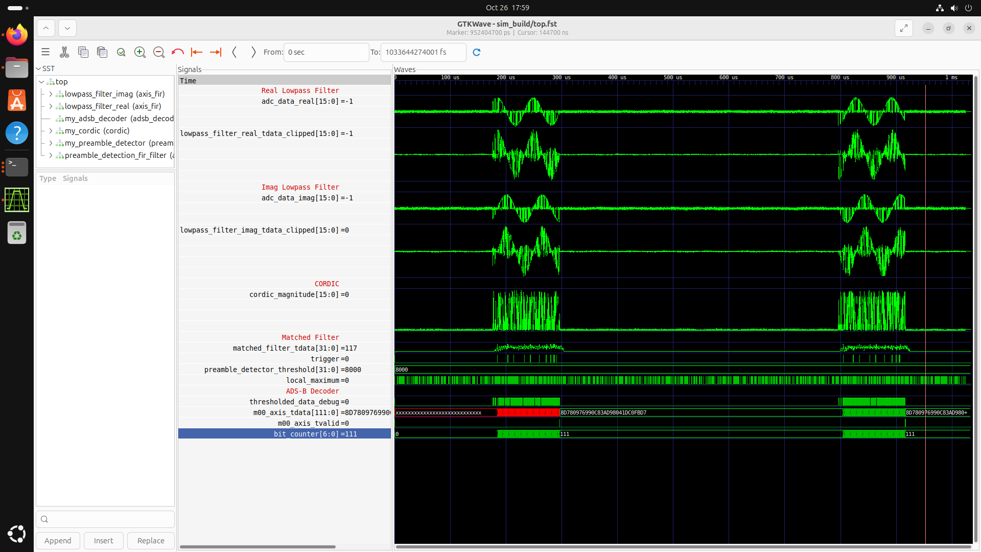
This testbench will run with either Vicoco or Icarus. The signed math stuff that differs between them has been done for you already, but if you want the certainty of testing in Vicoco, then uncomment lines 16 and 228 (and comment out 15 and 227) of the testbench.
Once you have it working in simulation reliably, it's time to go into Vivado. The entire structure we have given you, including top.sv, will get wrapped up in one big IP that takes in I/Q data from iq_framer and spits out ADS-B data over a 128-bit-wide AXI bus (112-bit AXI breaks the DMA, apparently, so we're padding it out with zeroes). The wrapper for the IP will set the coefficients and thresholds. If we had more time, we would make the thresholds settable via MMIO.
Download the wrapper for the IP here
Yes, I am setting the coefficients with gigundous constants. Yes, there are smarter ways to do this like $readmemh. NOTE that the thresholds set here are actually a bit different to the ones set by the testbench. These thresholds seem to work well on the real-life signals. They were determined experimentally.
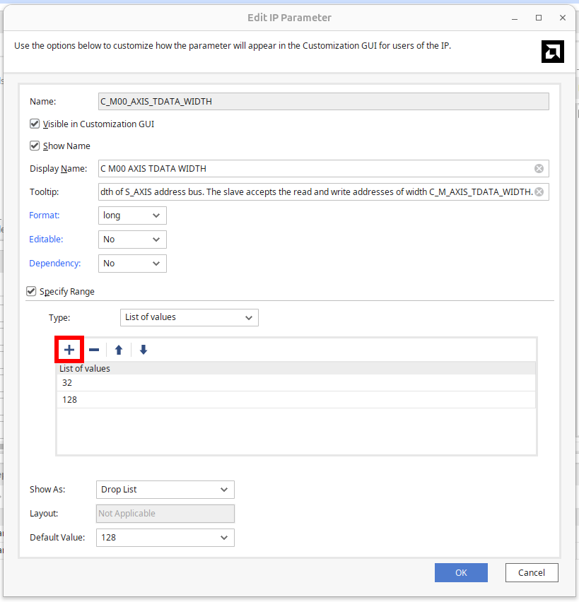
When you attempt to package this IP, Vivado will throw a hissy fit because of the 128-bit AXI bus. Go to the "Customization GUI" step of the IP Packager and double-click on C_M00_AXIS_TDATA_WIDTH:
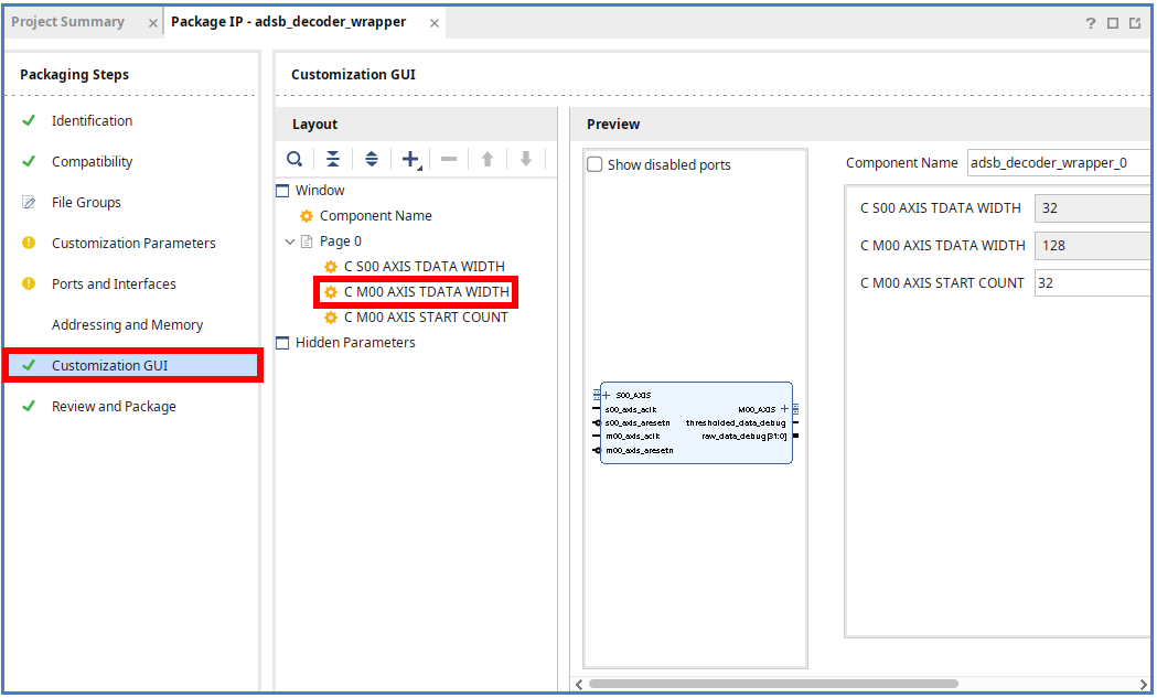
This will open an "Edit IP Parameter" window where you can use the "+" button to add "128" to the list of valid values:
Make sure to merge any changes it wants merged, then package the IP.
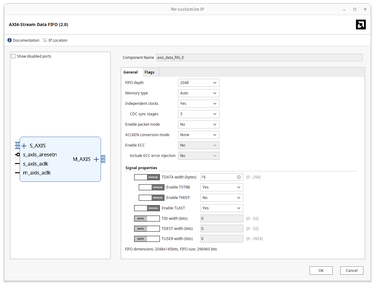
You can reuse the project/block diagram from the previous lab, but delete the CIC filters. We are using the same sample rate and clocking setup as the previous lab (64 MSps, 64 MHz clock, no clocking wizards). iq_framer should feed right into the input of the ADS-B decoder IP. The output of the ADS-B decoder IP should go into the FIFO, for which you'll need to change the width to 128 bits (16 bytes):
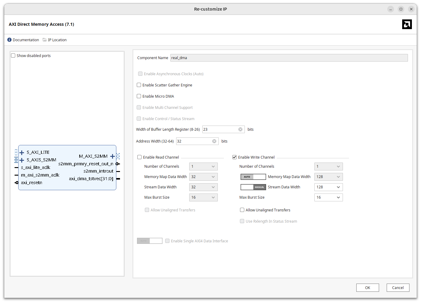
Make sure TLAST is enabled. Since every ADS-B squitter is its own separate message, the ADS-B decoder IP will send TLAST high with every message. The width of the DMA should also be set to 128 bits (this may happen automatically if you set it to auto and connect it to the output of the FIFO):
The full block diagram should look like this:
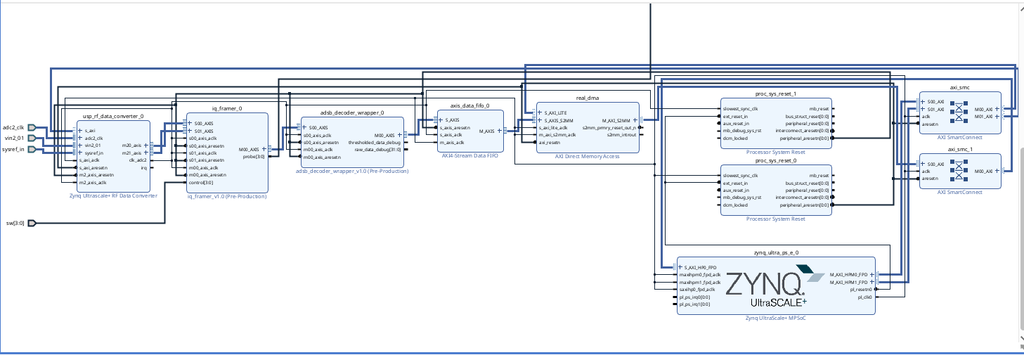
View a PDF of the block diagram here if you want to zoom in
Build it! We have written the Python side for you already (you may need to change the name of the bitfile if yours is different):
Download our Jupyter notebook for the PS side here
We could have made you do a bunch of bit manipulation in Python to extract latitude/longitude/altitude/etc. from the squitters, but there's no real reason to, so we are using the PyModeS library. You will need to run !pip install pyModeS==2.21.1 in a cell of the notebook to install the pyModeS library into the Pynq virtualenv (the exclamation mark runs the command in the underlying Linux shell, rather than in Python).
If you get an error about Numpy 2 not being compatible with Pynq, run !pip install numpy==1.26.4 in a separate cell of the notebook, then shutdown and reopen the notebook (see the File menu).
Remember to set your switches so that iq_framer is sending the I/Q data, not the debugging counters.
That's it! The number of planes is lower at night, so you may not see them if you are testing late at night. We have one antenna and LNA (the black box that says SAWBird). This works best with the antenna close to the window, so I have mounted it there and cabled it over to the 6.S965 area with some extra length to allow moving it around. You can unscrew the labeled SMA cable that goes to the RFSoC at station 45 and move it to your RFSoC on ADC B (same port we used for the FM lab). Don't leave it stretched through an area where somebody will trip over it and break the connector off an RFSoC. If you have no signal, check that somebody has not unplugged the LNA's power supply by the window (there should be a light on the LNA).
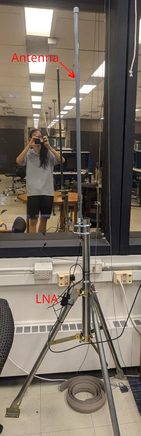
As an aside, the technology to do this is very achievable. The antenna is around $100 (most of which comes from it being weatherproofed and not anything you couldn't make yourself with some wire and a stick) and the low-noise amplifier (LNA) is around $80. I would also like to emphasize that you don't need a $12,000 FPGA to do this--people make ADS-B decoders using microcontrollers and external mixing. ADSBExchange actually works using a network of volunteers with low-cost ADS-B receiver setups (usually a USB radio dongle and a Raspberry Pi).
Check ADSBExchange to see if there are planes in the local area. The notebook should print out data like this:
Message: 8dac95165907a03f94a1702232aa
                ICAO address: ac9516
             Downlink Format: 17
                    Protocol: Mode-S Extended Squitter (ADS-B)
                        Type: Airborne position (with barometric altitude)
                  CPR format: Even
                CPR Latitude: 0.0620880126953125
               CPR Longitude: 0.3153076171875
                    Altitude: 450 feet
8dac95165907a03f94a1702232aa

                     Message: 8da38af8ea0bd8ee655c08bb2743
                ICAO address: a38af8
             Downlink Format: 17
                    Protocol: Mode-S Extended Squitter (ADS-B)
                        Type: Target State and Status
                     Subtype: 1
           Selected altitude: 6016 feet
             Altitude source: MCP/FCU
 Barometric pressure setting: 1027.2 millibars
            Selected Heading: 70.3125 °
8da38af8ea0bd8ee655c08bb2743

                     Message: 8da38af8e1121b00000000772667
                ICAO address: a38af8
             Downlink Format: 17
                    Protocol: Mode-S Extended Squitter (ADS-B)
8da38af8e1121b00000000772667

                     Message: 8da38af8582947c1c30f1b60a8fa
                ICAO address: a38af8
             Downlink Format: 17
                    Protocol: Mode-S Extended Squitter (ADS-B)
                        Type: Airborne position (with barometric altitude)
                  CPR format: Odd
                CPR Latitude: 0.9392166137695312
               CPR Longitude: 0.5295028686523438
                    Altitude: 7100 feet
8da38af8582947c1c30f1b60a8fa
You can search the ICAO addresses in ADSBExchange to confirm that you are seeing real data (although the fact that we are checking the CRCs makes false data unlikely). Note that the latitudes and longitudes are encoded using a scheme called Compact Position Representation (CPR). You can read about how to translate that into global lat/lon here. Feel free to try to decode that or to download a library that does it for you.
UPDATE AS OF 2 PM EDT on Nov. 4, 2025: the LNA died sometime this morning (power LED no longer lights up). The checkoff is just showing that it works in simulation for now. Working on replacing the LNA.
UPDATE AS OF 4 PM EDT on Nov. 4, 2025: the LNA seems be working fine, even though the power LED does not light up. Manufacturer claims that "sometimes the LEDs burn out." You should be able to test with the antenna, but let us know if you see no squitters in 5 minutes of observing.
Show that your ADS-B decoder works with our testbench in simulation and that it synthesizes. Depending on the time of day, optionally show that it actually decodes real ADS-B packets over the air.