Return to the Video Pipeline
Please Log In for full access to the web site.
Note that this link will take you to an external site (https://shimmer.mit.edu) to authenticate, and then you will be redirected back to this page.
The Setup
For a second look at DMA, instead of sending data down into the PL and then getting it back up (like we did previously), we're instead going to just harvest some data that originated in the PL side, specifically some video. We'll assume you've already got a working version of the week 03 video pipeline working since we're just going to modify it and add some additional functionality.
BEFORE YOU START THIS LAB STRONGLY CONSIDER MAKING A FULL COPY OF YOUR WEEK 3 VIVADO PROJECT SO THAT IF YOU MESS IT UP, YOU CAN EASILY RESTART! If you don't want to do the whole git thing, possibly just consider copy-pasting the entire project folder somewhere else and calling it like lab03_backup so that you can bring it back over just in case.
The additional functionality we'll add to your current Lab 3 will involve:
- Adding a AXI-DMA module, with only a write channel activated.
- Adding a data-framer module (that you write) to bring in bursts of video data into an AXI Stream.
- Adding in a two-clock AXIS FIFO to handle clock domain crossing.
- Very carefully ensuring that all the clocks get wired up correctly and all AXI channels go where they need to.
- Run some python and get some grabs of video like shown below.
This lab could potentially form the basis of a final project where you build a matched filter/kernel (likely in 2D) which scans, in real time, incoming data and when certain signatures are found, sub-regions of the whole image are directed up for some form of higher-level processing, either in Python or else where on the FPGA. I don't know, I'm not an ideas person, but you are.
This should be a pretty quick lab. Should.
Open The Old Project and Update
Ok with your lab 3 up and looking good, let's begin.
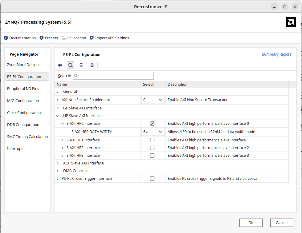
Zynq Processor
Update the Zynq processing system to have a 64 bi HP AXI Slave port:
While you're in the Zynq configuration settings, go and make sure that FCLK_CLK0 is set to be 100 MHz. Likely when you run things with Pynq it won't actually start at 100 MHz but we can always set it via the software manually. The important thing is for the toolchain to know to expect 100 MHz during build to meet timing.
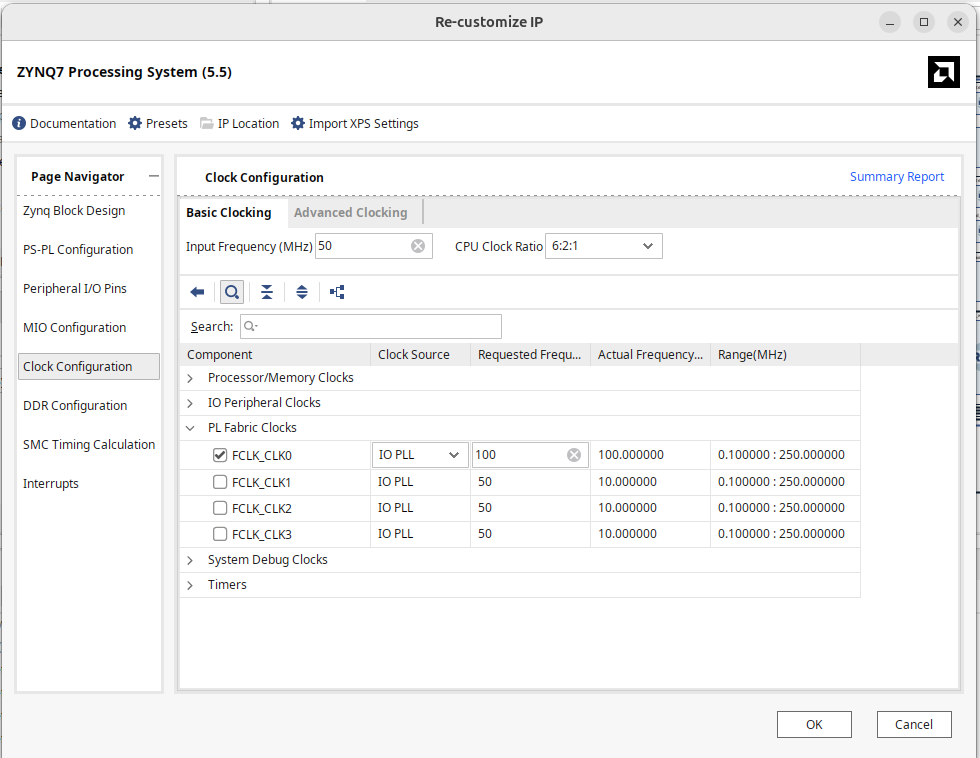
100 MHz is going to be particularly important in this lab since we're going to be feeding data from the video stream into the DMA. The pixels on 720p video will be coming in at 74.25MHz. To avoid traffic build-ups/hiccups we're going to want to make sure that we can consume data faster than we produce it during the bursts that we trigger (otherwise we'd need some sort of memory buffer/write logic and we don't want to deal with that here.)
Also note that you'll likely have to adjust the clock to 100 manually when Python starts up.
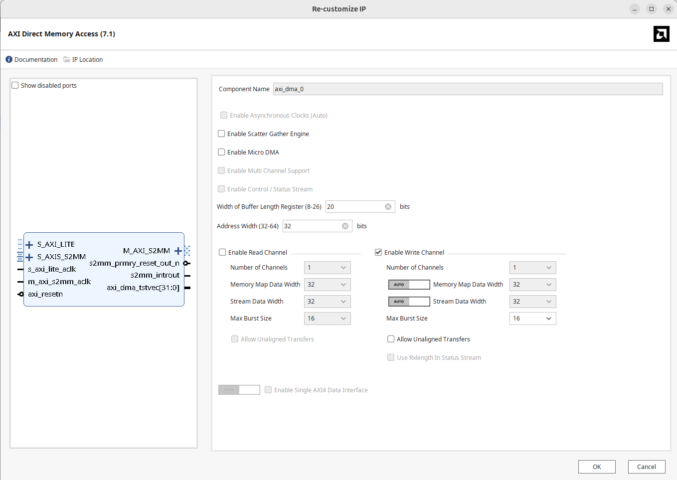
DMA
Let's add another regular AXI DMA module (same as the previous project). This time you only need activate the write channel (since we'll be sending data in from the FPGA side and not listening for anything from the processor side). We also don't need it to be wicked large since we'll only be sending up relatively small (~64K data bursts)
Data Framer
OK we now need a device that grabs pixels and sends them up to the processor via the DMA write channel. This module should frame data for consumption by the DMA engine.
For the DMA stream to work correctly, TLAST signals are extremely important, If those don't get sent up, or if those get sent up too late, by even a single clock cycle, relative to what the DMA engine was told to expect, it can cause the whole DMA engine to hang and/or cause catastrophic crashes on the Pynq side.
For example, if you have something like this in Pynq:
n=65536
out_buffer = allocate(shape=(n,), dtype=np.int32)
dma.recvchannel.transfer(out_buffer)
dma.recvchannel.wait()
What has happened is the DMA engine has now been prepped to expect 65,536 data beats sent in on its S_AXIS_S2MM port, with the last beat having the tlast signal asserted. If this does not happen...such as:
- You send up 65,537 data beats with
tlastasserted on the last one or... - You send up 65,536 data beats and never assert
tlastor even... - You send up 10,000 data beats and assert
tlaston the 10,000th...
The system may hang indefinitely. In actuality, the third one may make it through fine, however there will be nothing of meaning in the last 55,536 words in memory which could be another issue.
In the previous DMA assignment, since the data we were processing originated from the DMA engine's M_AXIS_MM2S channel, it took care of framing the stream burst with a tlast and all we had to do was make sure we propagate it forward. Now, however, the data (our video) is originating outside the AXI ecosystem and it is our job to convert it to AXI-stream and frame it as expected. So we need to make a module to do this.
Here is a Verilog "wrapper" file for what we want to build.
module data_framer_w #
	(
		parameter integer C_M00_AXIS_TDATA_WIDTH	= 32
	)
	(
        input wire pixel_clk, //driven by video pixel clock
        input wire [23:0] pixel_data, //24 bit true color video data
        input wire trigger,

		// Ports of Axi Master Bus Interface M00_AXIS
		input wire  m00_axis_tready,
		output wire  m00_axis_tvalid, m00_axis_tlast,
		output wire [C_M00_AXIS_TDATA_WIDTH-1 : 0] m00_axis_tdata,
		output wire [(C_M00_AXIS_TDATA_WIDTH/8)-1: 0] m00_axis_tstrb
	);

    data_framer mdf
    (   .pixel_clk(pixel_clk),
        .pixel_data(pixel_data),
        .trigger(trigger),
        .m00_axis_tready(m00_axis_tready),
        .m00_axis_tvalid(m00_axis_tvalid),
        .m00_axis_tlast(m00_axis_tlast),
        .m00_axis_tdata(m00_axis_tdata),
        .m00_axis_tstrb(m00_axis_tstrb)
    );
endmodule
Then of course, so we don't have to use nasty old Verilog, we have this wrapping a SystemVerilog module that should be doing the actual logic:
#Make a .sv file
module data_framer #
	(
		parameter integer C_M00_AXIS_TDATA_WIDTH	= 32
	)
	(
        input wire pixel_clk,
        input wire [23:0] pixel_data,
        input trigger,
		// Ports of Axi Master Bus Interface M00_AXIS
		input wire  m00_axis_tready,
		output logic  m00_axis_tvalid, m00_axis_tlast,
		output logic [C_M00_AXIS_TDATA_WIDTH-1 : 0] m00_axis_tdata,
		output logic [(C_M00_AXIS_TDATA_WIDTH/8)-1: 0] m00_axis_tstrb
	);

    //You want to send up TLAST-framed bursts of data that are 2**16 in length
    //update and test this module to make sure that's happening.

    always_ff @(posedge pixel_clk)begin
        m00_axis_tvalid <= 0; //?? How often should data be valid (CHANGE ME)?
        m00_axis_tlast <= 0; //when should TLAST be high (CHANGE ME)?
        m00_axis_tdata <= {8'b0, pixel_data}; //i'll give this one to you
        m00_axis_tstrb <= 4'b1111; //let's just say all bits are good all the time.
    end
endmodule
Your job is to finish this data_framer. This should not be super complicated. Upon pressing as a trigger, (and I would strongly recommend not only debouncing but running that trigger signal through some synchronizer flops first), the data_framer module should release a burst of 65,536 values of video. During the burst, the video data cannot be stopped. You must always have valid data. Whether or not downstream can accept that will hopefully be resolved with a FIFO in the next step. In order to ensure you're sending up correctly sized bursts, th tlast signal must fire only after 65,536 valid/ready data beats (meaning if a handshake did not take place, you just throw that piece of data out. Ideally the FIFO is large enough to absorb any momentary backpressure hiccups).
Make sure that happens! Finish the code above (shouldn't be more than a few lines), consider running it through some quick AXI-Stream verification like you did with your FIR, and then integrate into the project like you've been doing the last few weeks.
For the love of Euler's formula, please testbench this module before spending hours debugging it in Vivado. You have an AXIS monitor...make sure after a trigger, 65,536 samples (with an ending TLAST) get sent out...no more, no less. Also make sure it is repeatable. Possibly even consider testing both the data_framer and data_framer_wrapper.
AXIS FIFO
The last piece to add is an AXIS FIFO. The FIFO serves two roles:
- It serves as a means to absorb short-term data hiccups and backpressure that may originate with the ultimate sink of our AXI Stream, the DMA write port. A shallow FIFO of 512 words will suffice for this, but if you want to go larger, be my guest.
- It will handle the clock-domain cross from our pixel clock domain into our AXI-clock domain. A FIFO is a great way to do this since they will get generated using the BRAM primitives on the FPGA which are capable of being true dual-clock two-port memory stores.
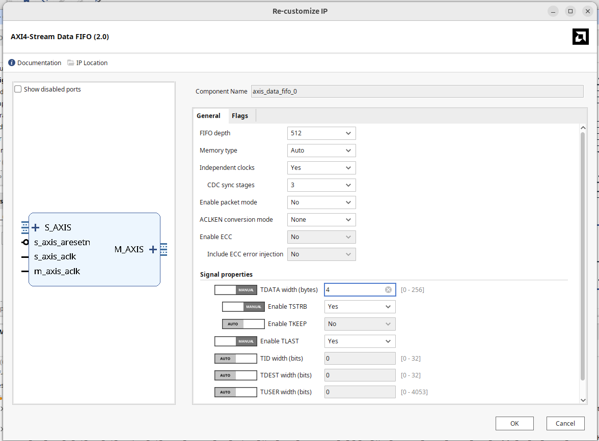
One side of this FIFO is going to live on the Pixel clock domain (the S side). For its reset signal, go ahead and make an always-1 inline constant and tie it its reset to it (s_axis_aresetn).
Wiring this Mess Together
OK this is where you're going to need to be careful. Vivado is going to have hard time knowing exactly what you want to do, so we need to help it, first wire up:
- The output of your
data_framerto the input of your AXIS FIFO (Sport) - The clock of your
data_framerand the clock of your AXI_FIFO to the pixel clock. - The output of your AXIS FIFO (
Mport) to the streaming input of your DMA (S2MM). - All the clocks of the DMA to
FCLK_CLK0 - The AXI Clock of the FIFO
Mport toFCLK_CLK0.
With those in place, that might be enough for Vivado to intelligently auto-connect everything. It'll automatically instantiate some interconnects and things that are needed to merge the multiple AXI busses related to the DMA (among other things). But in my experience, Vivado might try to mess up your clocks, so be on the lookout for that. ALL THE AXI stuff should be on FCLK_CLK0 except for the S side of the AXIS FIFO (including your MMIO controller from lab 03).
During build you may get a critical warning like the following
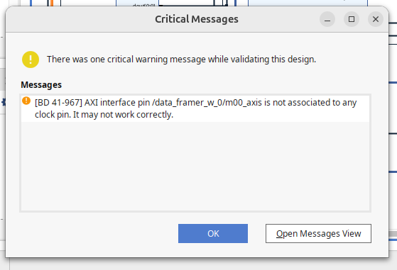
If you need to perform "surgery", be careful deleting wires. If you click on a global wire and then just do delete, it will wipe out the whole thing and then you lose all the connections, good and bad. Instead what you're going to want to do is right click on the actual ports (in the GUI) and there should be an option to "disconnect"
Finishing Up
Assuming the build works, head on in and either make (or modify) a notebook so that it grabs and displays lines of video. the following should basically do that.
from pynq import PL
PL.reset() #important fixes caching issues which have popped up.
from pynq import Overlay  #import the overlay module
ol = Overlay('./design_1_wrapper.bit')  #locate/point to the bit file
#import pprint
#pprint.pprint(ol.ip_dict)
dma = ol.axi_dma_0
from pynq import Clocks
#Clocks.fclk0_mhz = 100
print(f"FCLK0: {Clocks.fclk0_mhz:.6f}MHz")
Clocks.fclk0_mhz = 100
print(f"FCLK0: {Clocks.fclk0_mhz:.6f}MHz")
import numpy as np
import time
%matplotlib notebook
import matplotlib.pyplot as plt
from pynq import allocate
n = 65536
n_vals = np.linspace(0, n-1, n)
out_buffer = allocate(shape=(n,), dtype=np.int32)
dma.recvchannel.transfer(out_buffer)
dma.recvchannel.wait()
bitmask = np.uint32(0x000000FF)
g = out_buffer & bitmask
b = (np.right_shift(out_buffer, 8)) & bitmask
r = (np.right_shift(out_buffer, 16)) & bitmask
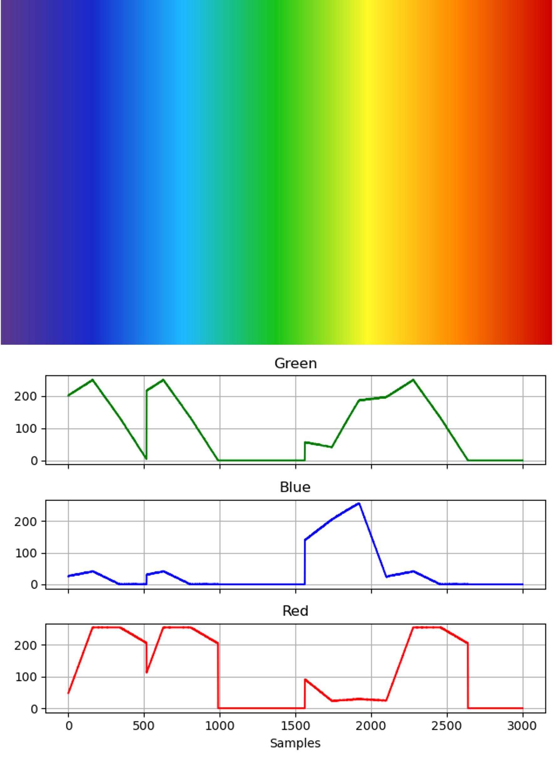
fig, axs = plt.subplots(nrows=3, ncols=1, sharex=True)
#plot only 3000 lines since the zynq 7000 cores are anemic
STOP = 3000
axs[0].grid(True)
axs[1].grid(True)
axs[2].grid(True)
axs[0].plot(n_vals[:STOP],g[:STOP],'g-')
axs[0].set_title('Green')
axs[1].plot(n_vals[:STOP],b[:STOP],'b-')
axs[1].set_title('Blue')
axs[2].plot(n_vals[:STOP],r[:STOP],'r-')
axs[2].set_title('Red')
plt.xlabel('Samples')
plt.tight_layout()
plt.show()
out_buffer.close()
Find an image or video or something that has obvious color patterns that could be deduced from simple visual inspection (videos of squirrels may be harder to predict, but rainbows, flags, simple images might be much more conducive to testing.) You should have something looking like the image at the top of the page. Run the code, and then push your button.
Because our FIFO/framing infrastructure is super simple, there's a good chance you may have a discontinuity in your frame data depending on if the FIFO was already filled up when commands were called. This could be fixed with more control and/or some sort of trigger mechanism (like we did in week 2) to prevent the FIFO from filling up automatically, but to be honest, I'm really tired, boss, and I don't feel like doing that. What we have is good enough for government work right now.
OK. when good, get the checkoff.
Show your working MMIO-controlled video streaming system to a staff member.
