AXIS Interface
Talking to AXIS
Please Log In for full access to the web site.
Note that this link will take you to an external site (https://shimmer.mit.edu) to authenticate, and then you will be redirected back to this page.
A Generic AXIS Module
For this week we want to build a couple of AXI Streaming (AXIS) modules. One we'll basically give to you, and the second, (the hard part of which should have been figured out in week 3 when you built the 15 tap FIR) you'll create. As we've talked about in class, AXI Streaming is part of the AMBA/AXI4 specification, and it is the simplest of the three classes (AXI Full, AXI-Lite, and AXI Streaming). This simplicity comes from the fact that:
- Only Data is moved around: There are not official address channels, response channels, etc... you just move data.
- Transactions occur unidirectionally: Data only moves from Master to Slave device. There is no backwards movement.
- It can be very high throughput. Since everything in an AXI Stream is moving data in the same direction, it can be very amenable to high-throughput "stream" processing.
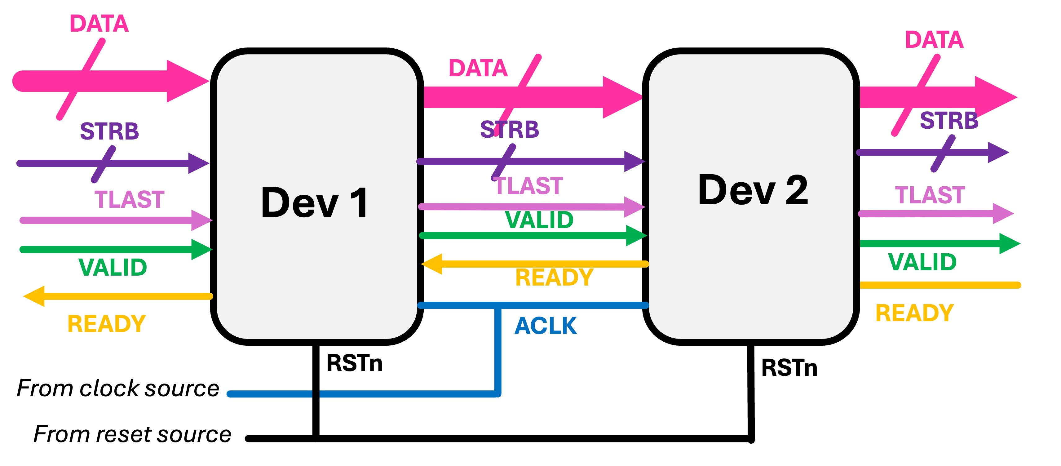
When it comes time to write an AXIS module, we'll worry about the following sets of signals on a bus:
axis_aclk: The clock of the channel. Data is sampled on the rising edge of this clock.axis_aresetn: The reset of the channel (active low). Both parties should reset during this signalaxis_tdata [31:0]: The payload of the channel. This is 32 bits (standard) of data. It can be used for whatever you want/interpretted in any way so desired (int,float, char, custom, whatever)...but this is the stuff getting moved around and what it is all for.axis_tvalid: The signal that a producer/master indicates it has valid data.axis_tready: The signal that a consumer/slave indicates that it is ready for data.axis_tstrb[3:0]: A signal that can be used to indicate which of the bytes in the data are valid/to be used. Can be set to4'b1111by default.axis_tlast: A signal indicating that the data on that clock cycle is the "last" of that set. This is useful in indicating the end of a data burst or packet. Often times final-endpoint consuming devices will be looking forTLASTsignasl to know when to stop trying to read.
Some of these will generally be parameterizable, but for our starter cases now, we'll just keep some dimensions and/or their existence non-optional so we have fewer things to mess us up. All signals propagate downstream with the notable exception of tready which propagates upstream and is a form of backpressure, allowing downstream devices to pause the pipeline and avoid data loss. Ideally, tready will propagate upstream quickly to avoid data collisions within/between modules (think of a bunch of cars driving in a line and the first one brakes...it is often the fact that cars further back don't know of the braking that causes an accident. If they'd all know that the first just applied brakes they could do the same.)
A basic AXIS module in Verilog is shown below:
module general_wrapper #
	(
		parameter integer C_S00_AXIS_TDATA_WIDTH	= 32,
		parameter integer C_M00_AXIS_TDATA_WIDTH	= 32,
	)
	(
		// Ports of Axi Slave Bus Interface S00_AXIS
		input wire  s00_axis_aclk, s00_axis_aresetn,
		input wire  s00_axis_tlast, s00_axis_tvalid,
		input wire [C_S00_AXIS_TDATA_WIDTH-1 : 0] s00_axis_tdata,
		input wire [(C_S00_AXIS_TDATA_WIDTH/8)-1: 0] s00_axis_tstrb,
		output logic  s00_axis_tready,

		// Ports of Axi Master Bus Interface M00_AXIS
		input wire  m00_axis_aclk, m00_axis_aresetn,
		input wire  m00_axis_tready,
		output logic  m00_axis_tvalid, m00_axis_tlast,
		output logic [C_M00_AXIS_TDATA_WIDTH-1 : 0] m00_axis_tdata,
		output logic [(C_M00_AXIS_TDATA_WIDTH/8)-1: 0] m00_axis_tstrb
	);

endmodule
The simplest thing you could do with from this would be to make an AXIS "wire"...a completely useless passthrough object. This wouldn't do anything, but it at least shows your minimum viable AXIS, where the term "viable" is used very, very loosely.
module axis_wire #
	(
		parameter integer C_S00_AXIS_TDATA_WIDTH	= 32,
		parameter integer C_M00_AXIS_TDATA_WIDTH	= 32,
	)
	(
		// Ports of Axi Slave Bus Interface S00_AXIS
		input wire  s00_axis_aclk, s00_axis_aresetn,
		input wire  s00_axis_tlast, s00_axis_tvalid,
		input wire [C_S00_AXIS_TDATA_WIDTH-1 : 0] s00_axis_tdata,
		input wire [(C_S00_AXIS_TDATA_WIDTH/8)-1: 0] s00_axis_tstrb,
		output logic  s00_axis_tready,

		// Ports of Axi Master Bus Interface M00_AXIS
		input wire  m00_axis_aclk, m00_axis_aresetn,
		input wire  m00_axis_tready,
		output logic  m00_axis_tvalid, m00_axis_tlast,
		output logic [C_M00_AXIS_TDATA_WIDTH-1 : 0] m00_axis_tdata,
		output logic [(C_M00_AXIS_TDATA_WIDTH/8)-1: 0] m00_axis_tstrb
	);

    assign m00_axis_tdata = s00_axis_tdata; //these all going downstream
    assign m00_axis_tvalid = s00_axis_tvalid;
    assign m00_axis_tlast = s00_axis_tlast;
    assign m00_axis_tstrb = s00_axis_tstrb;
    assign s00_axis_tready = m00_axis_tready; //going upstream

endmodule
The whole point of this framework is to do something, however, so let's see an example of an AXIS module that actually does something.
Here's a streaming module, called j_math (short for "joe math", but you can call yours whatever you want). that takes in a number x and calculates 3\cdot x + 10000. It does it using one layer of flip flops. This is good practice since a multiply-add will take some compute time and if we're going to be stacking things, we don't want to introduce long combinational paths.
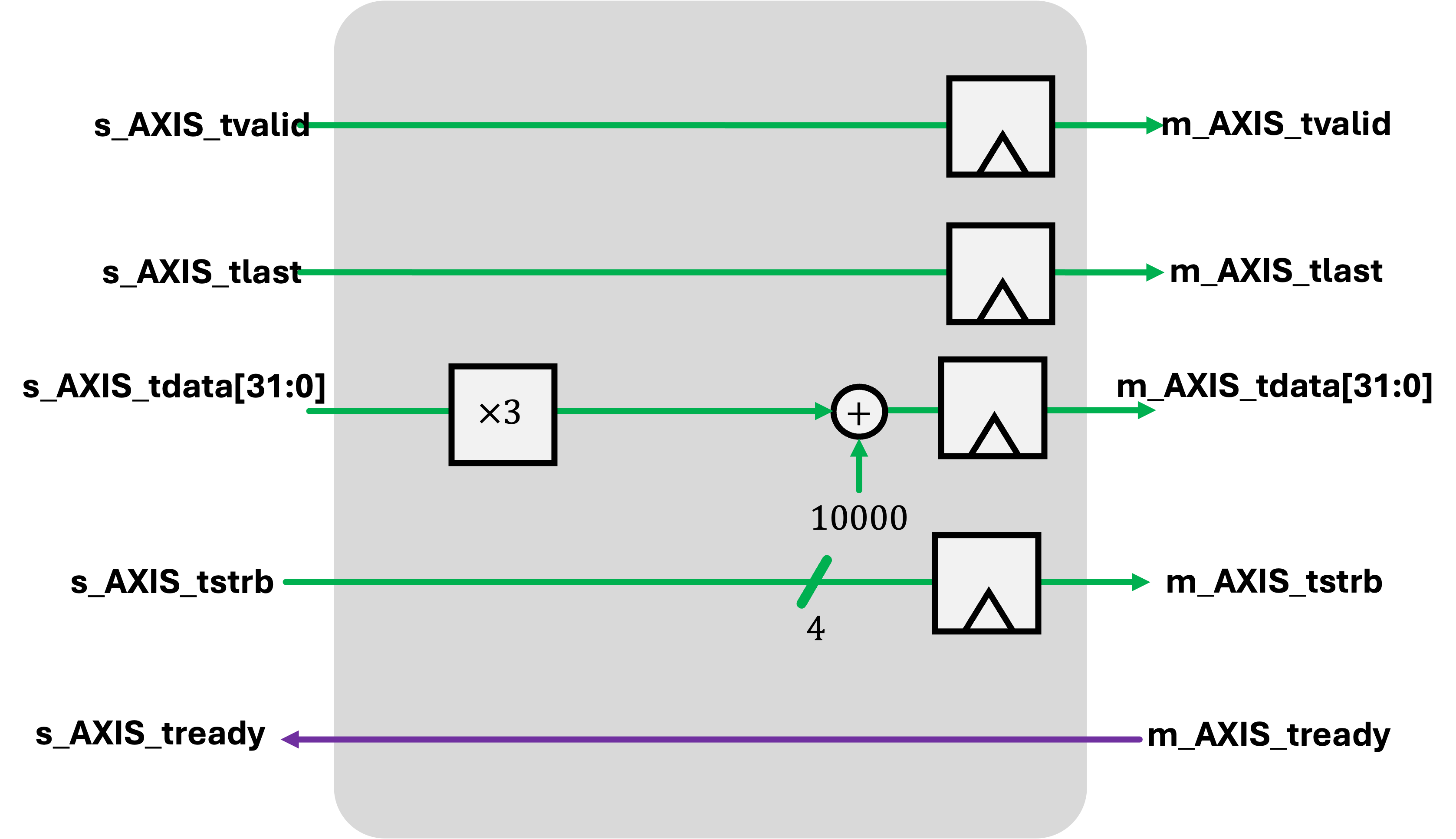
Notice all the with-data signals are pipelined appropriately to ensure that the metadata keeps up with the signals.
module j_math #
	(
		parameter integer C_S00_AXIS_TDATA_WIDTH	= 32,
		parameter integer C_M00_AXIS_TDATA_WIDTH	= 32
	)
	(
		// Ports of Axi Slave Bus Interface S00_AXIS
		input wire  s00_axis_aclk, s00_axis_aresetn,
		input wire  s00_axis_tlast, s00_axis_tvalid,
		input wire [C_S00_AXIS_TDATA_WIDTH-1 : 0] s00_axis_tdata,
		input wire [(C_S00_AXIS_TDATA_WIDTH/8)-1: 0] s00_axis_tstrb,
		output logic  s00_axis_tready,

		// Ports of Axi Master Bus Interface M00_AXIS
		input wire  m00_axis_aclk, m00_axis_aresetn,
		input wire  m00_axis_tready,
		output logic  m00_axis_tvalid, m00_axis_tlast,
		output logic [C_M00_AXIS_TDATA_WIDTH-1 : 0] m00_axis_tdata,
		output logic [(C_M00_AXIS_TDATA_WIDTH/8)-1: 0] m00_axis_tstrb
	);

    logic m00_axis_tvalid_reg, m00_axis_tlast_reg;
    logic [C_M00_AXIS_TDATA_WIDTH-1 : 0] m00_axis_tdata_reg;
    logic [(C_M00_AXIS_TDATA_WIDTH/8)-1: 0] m00_axis_tstrb_reg;

    assign m00_axis_tvalid = m00_axis_tvalid_reg;
    assign m00_axis_tlast = m00_axis_tlast_reg;
    assign m00_axis_tdata = m00_axis_tdata_reg;
    assign m00_axis_tstrb = m00_axis_tstrb_reg;
    assign s00_axis_tready = m00_axis_tready;

    always_ff @(posedge s00_axis_aclk)begin
        if (s00_axis_aresetn==0)begin
            m00_axis_tvalid_reg <= 0;
            m00_axis_tlast_reg <= 0;
            m00_axis_tdata_reg <= 0;
            m00_axis_tstrb_reg <= 0;
        end else begin
            m00_axis_tvalid_reg <= s00_axis_tvalid;
            m00_axis_tlast_reg <= s00_axis_tlast;
            m00_axis_tdata_reg <=3*s00_axis_tdata+10000;
            m00_axis_tstrb_reg <= s00_axis_tstrb;
        end
    end
endmodule
This module implementation does have one flaw, however, and we'll explore it a bit as we go through this page.
Cocotb Bus
Here is a starter file for this page's work..
OK now we want to testbench this stuff but as our systems get more and more complex, it is going to get harder and harder to try to poke at stuff and remember what we wanted to get and so on. You already will kinda know what I mean just from having written testbenches in the past. They can get nasty.
One step toward keeping this mess under control is to be able to just easily throw stuff at the input of a device using high-level commands. And also have a device that can listen to what goes in and out and can provide some level of interpretation to what is happening at a level more readable than us just counting clock cycles.
Towards this end we're going to develop a monitor and a driver for our AXIS Bus, two core elements in a modern testing framework (see lecture 07).
AXIS Monitor
Go and install cocotb_bus. You can do this by doing pip install cocotb_bus. Create a new cocotb file (you can base it off of your SPI testbenches from last week). Update the names and things as needed, of course.
We'll be using some new libraries:
from cocotb_bus.bus import Bus
from cocotb_bus.drivers import BusDriver
from cocotb_bus.monitors import Monitor
from cocotb_bus.monitors import BusMonitor
import numpy as np
Now cocotb_bus has several very useful constructs in it as we mentioned in class.
One of them is Bus, which is a Python class that groups a set of signals. We'll not use Buses on their own much but we will use they for the core part of several other devices. The first is the Bus Monitor.
The BusMonitor is a device that is attached to a bus and then upon creation starts running and monitoring the bus. While monitoring, it can look for particular types of signals and then carry out task like reporting and logging them when they see relevant things appear. You'll rarely use the BusMonitor class on its own, you'll instead make customized versions of the class using class inheritance like Python allows you to do.
An example of a BusMonitor implementation is shown below. I wrote it to basically "Monitor" an AXIS bus and report what it sees. Using the rules of AXI Streaming, (most importantly, when ready and valid are high on a rising edge, a exchange has taken place, the system keeps track of the number of transactions it has observed as well as attributes of them. Eventually we'll want to send them off to a special spot (self._recv which can trigger callbacks and things...we'll talk about in the future), but for now we'll just have it print what it sees!
class AXIS_Monitor(BusMonitor):
    """
    monitors axi streaming bus
    """
    transactions = 0 #use this variable to track good ready/valid handshakes
    def __init__(self, dut, name, clk, callback=None):
        self._signals = ['axis_tvalid','axis_tready','axis_tlast','axis_tdata','axis_tstrb']
        BusMonitor.__init__(self, dut, name, clk, callback=callback)
        self.clock = clk
        self.transactions = 0
        self.dut = dut
    async def _monitor_recv(self):
        """
        Monitor receiver
        """
        rising_edge = RisingEdge(self.clock) # make these coroutines once and reuse
        falling_edge = FallingEdge(self.clock)
        read_only = ReadOnly() #This is
        while True:
            #await rising_edge #can either wait for just edge...
            #or you can also wait for falling edge/read_only (see note in lab)
            await falling_edge #sometimes see in AXI shit
            await read_only  #readonly (the postline)
            valid = self.bus.axis_tvalid.value
            ready = self.bus.axis_tready.value
            last = self.bus.axis_tlast.value
            data = self.bus.axis_tdata.value #.signed_integer
            if valid and ready:
                self.transactions+=1
                thing = dict(data=data.signed_integer,last=last,
                             name=self.name,count=self.transactions)
                self.dut._log.info(f"{self.name}: {thing}")
                self._recv(data.signed_integer)
This monitor was written with some reusability in mind. Because both the input and output of our streaming modules use the AXIS protocol, we should hopefully be able to apply it to both sides. In fact, some aspects of the BusMonitor class are intentionally designed to allow for this. For example, the annoying naming convention of the Master and Slave Busses atually does have a usage here. We can create two instances of this AXIS_Monitor like so:
    inm = AXIS_Monitor(dut,'s00',dut.s00_axis_aclk) #in monitor
    outm = AXIS_Monitor(dut,'m00',dut.s00_axis_aclk) #out monitor
and if you dig through the source code, you'll see that the internal signals we specified as existing on our bus (such as axis_tdata are attached with an _ to the name of the bus s00 or m00, allowing the general name to refer to the specific instance with no problem.
Once you've set/initialized the two bus monitors (one on the input, one on the output), they'll run in the background monitoring the line and reporting (via prints) when they see something.
Deploying them in the test is very easy. For example you could do:
@cocotb.test()
async def test_a(dut):
    """cocotb test for seven segment controller"""
    inm = AXIS_Monitor(dut,'s00',dut.s00_axis_aclk)
    outm = AXIS_Monitor(dut,'m00',dut.s00_axis_aclk)
    cocotb.start_soon(Clock(dut.s00_axis_aclk, 10, units="ns").start())
    await Timer(10000,"ns")
Of course, right now we have no signals going into the device so these things are monitoring nothing.
Aside on Awaits
In the monitor above, you'll notice the lines that are associated with awaiting for the purpose of monitoring:
If the await sequence is:
            await rising_edge
            await falling_edge
            await read_only
            valid = self.bus.axis_tvalid.value
            ready = self.bus.axis_tready.value
            last = self.bus.axis_tlast.value
            data = self.bus.axis_tdata.value #.signed_integer
Or even just this:
            await falling_edge
            await read_only
            valid = self.bus.axis_tvalid.value
            ready = self.bus.axis_tready.value
            last = self.bus.axis_tlast.value
            data = self.bus.axis_tdata.value #.signed_integer
That means the values read in the lines after correspond to the values at the upcoming rising edge in the future. You may find doing it this way easier to understand and work with.
If alternatively you instead just use the following single await:
            await rising_edge
            valid = self.bus.axis_tvalid.value
            ready = self.bus.axis_tready.value
            last = self.bus.axis_tlast.value
            data = self.bus.axis_tdata.value #.signed_integer
This corresponds the values as they were right when the rising edge of the clock happened. In other words, they are the values for the current rising edge. This is because the RisingEdge trigger in Cocotb (and the VVP) fires immediately when the clock goes from 0 to 1. This means when that this trigger yields back, no signal (or line of Verilog) has yet had a chance to utilize or be evaluated due to that rising edge, so it is an effective snapshot of "just before" for the purposes of monitoring.
Remember! When you call await RisingEdge(clock.clock) it yields control to you (Python) when the VVP has just risen. Since that means lines that are activated for analysis such as always_ff @(posedge clock) thing <= trigger?thing+1:thing; have yet to be triggered (but will be after another iteration of Verilog run-time deltasteps, reading values right at this point will ensure you have access to signals like thing that prior to that line being evaluated. You may be able to think of ways where some race conditions could still be unreliable using only the RisingEdge and that is for sure true but if the Verilog was written properly (not mixing blocking assignments into sequential blocks, no conflicting assignments across blocks, etc...), the approach described should be fine.
Since monitors run in continuous loops, either way should work if utilized properly with minor exceptions at the very start of the simulation (when you're likely in reset mode anyways), as well as when they may message their values (on the preceding falling edge or at the rising edge). Be aware of these differences, but they should both work.
AXIS Driver
The second part we want to develop (And I'm not going to give all of it to you this time sorry), is the AXIS_Driver. Specifically this would perform the duty of setting signals on an AXIS channel. But if you think about it, there are two roles you can be on an AXIS channel: the M/Master/Manager or the S/Slave/Subordinate. And these roles are quite different. In an AXIS channel:
- The
M/Master/Manager setsdata,strb,last,valueandvalidand reacts to thereadyfrom theS/Slave/Subordinate. - The
S/Slave/Subordinate setsreadyand reacts todata,strb,last,valueandvalidfrom theM/Master/Manager.
So we need two types of drivers. We'll define a general base class called AXIS_Driver (itself based on the super Driver class), and then make subclasses from that M_AXIS_Driver and S_AXIS_Driver.
The Driver class on its own is another class that is very rarely used as it is, but is instead used as a prototype for more specific variants. Here the AXIS_Driver class has all the signals of the AXIS bus in it.
The async def _driver_send module is what we want to focus on and where most differentiation will occur. This method should really not be called directly. Instead we'll feed inputs to the class via a different mechanism. These values get placed in a queue like object and executed by _driver_send in order as they get processed.
What value needs to be is left completely open and this is where we can start specify transactions at a very high level. We do not want to be manually specifying which bits are going high with these instructions. We instead want to describe what type of transaction and have _driver_send know how to interpret and implement it.
With that in mind, for this week, we'll have a list of four commands for the different drivers:
- Two specifically for a
M/Master/Manager:{"type":"write_single", "contents": {"data": int, "last": int}}: A single data transfer should take place with valuedataand tlast set tolast.{"type":"write_burst", "contents": {"data": int array}}: A burst data transfer of each value inarray. Signal tlast should be 0 except on the last transfer of the burst.
- One specificaly for a
S/Slave/Subordinate:{"type":"read", "duration":int}: Read indurationdata beats
- One that can be used by either channel role:
{"type":"pause","duration":int}:- In the case of
M/Master/Manager:valid, andlastshould be set to 0 fordurationrising clock edges. - In the case of
S/Slave/Subordinate:readyshould be set to 0 fordurationrising clock edges.
- In the case of
A starting AXIS_Driver skeleton is provided below.
class AXIS_Driver(BusDriver):
    def __init__(self, dut, name, clk, role="M"):
        self._signals = ['axis_tvalid', 'axis_tready', 'axis_tlast', 'axis_tdata','axis_tstrb']
        BusDriver.__init__(self, dut, name, clk)
        self.clock = clk
        self.dut = dut
And from that we'll have two subclasses from that:
class M_AXIS_Driver(AXIS_Driver):
    def __init__(self, dut, name, clk):
        super().__init__(dut,name,clk)
        self.bus.axis_tdata.value = 0
        self.bus.axis_tstrb.value = 0xF
        self.bus.axis_tlast.value = 0
        self.bus.axis_tvalid.value = 0

    async def _driver_send(self, value, sync=True):
        rising_edge = RisingEdge(self.clock) # make these coroutines once and reuse
        falling_edge = FallingEdge(self.clock)
        read_only = ReadOnly() #This is
        if value.get("type") == "pause":
            await falling_edge
            self.bus.axis_tvalid.value = 0 #set to 0 and be done.
            self.bus.axis_tlast.value = 0 #set to 0 and be done.
            for i in range(value.get("duration",1)):
                await rising_edge
        else:
            pass
and
class S_AXIS_Driver(BusDriver):
    def __init__(self, dut, name, clk):
        AXIS_Driver.__init__(self, dut, name, clk)
        self.bus.axis_tready.value = 0

    async def _driver_send(self, value, sync=True):
        rising_edge = RisingEdge(self.clock) # make these coroutines once and reuse
        falling_edge = FallingEdge(self.clock)
        read_only = ReadOnly() #This is
        if value.get("type") == "pause":
            await falling_edge
            self.bus.axis_tready.value = 0 #set to 0 and be done.
            for i in range(value.get("duration",1)):
                await rising_edge
        else:
            pass
I've taken care of the M and S driver reacting to the pause command as well as their initialization commands. You need to do the rest. Note When starting each command, I begin at the falling edge of the AXI clock and end at a rising edge. Following a similar pattern for all drive sequences will allow them to stitch together neatly.
Testing
Let's use j_math as a testbench for our testbench... Here's a starter test.
A few things to note:
We connect a callback to both the input and output monitors. For the output monitor, the callback just appends the observed value to the sig_out_act list. For the input monitor, the callback triggers the j_math model which appends it to a sig_in list as well as a sig_out_exp array.
A third testbenching object is brought in in this testbench a Scoreboard. This class allows us to compare Monitor outputs and expected queues of data and will fail the simulation (in a nice way) if differences between actual and expected are observed. To see it in action, temporarily break the j_math_model function so that the expected and actual will differ. (don't forget to put it back when done).
For testing inputs, you can see we feed the M Driver with a number of different input sequences (that are randomized) as well as a very simple "always ready" command issued to the "S" side driver.
sig_in = [] #just for convenience
sig_out_exp = [] #contains list of expected outputs (Growing)
sig_out_act = [] #contains list of expected outputs (Growing)
def j_math_model(val):
    sig_in.append(val)
    result = 3*val + 10000
    sig_out_exp.append(result)


@cocotb.test()
async def test_a(dut):
    """cocotb test for AXIS jmath"""

    inm = AXIS_Monitor(dut,'s00',dut.s00_axis_aclk,callback=j_math_model)
    outm = AXIS_Monitor(dut,'m00',dut.s00_axis_aclk,callback=lambda x: sig_out_act.append(x))
    ind = M_AXIS_Driver(dut,'s00',dut.s00_axis_aclk) #M driver for S port
    outd = S_AXIS_Driver(dut,'m00',dut.s00_axis_aclk) #S driver for M port

    # Create a scoreboard on the stream_out bus
    scoreboard = Scoreboard(dut,fail_immediately=False)
    scoreboard.add_interface(outm, sig_out_exp)
    cocotb.start_soon(Clock(dut.s00_axis_aclk, 10, units="ns").start())
    await reset(dut.s00_axis_aclk, dut.s00_axis_aresetn,2,0)

    #feed the driver on the M Side:
    for i in range(50):
        ind.append({'type':'write_single', "contents":{"data": random.randint(1,255),"last":0}})
        ind.append({"type":"pause","duration":random.randint(1,6)})
    ind.append({'type':'write_burst', "contents": {"data": np.array(list(range(100)))}})
    ind.append({'type':'pause','duration':2}) #end with pause

    #feed the driver on the S Side:
    #always be ready to receive data:
    outd.append({'type':'read', "duration":1000})

    await ClockCycles(dut.s00_axis_aclk, 500)
    #if transaction counts on input and output don't match, raise an issue!
    assert inm.transactions==outm.transactions, f"Transaction Count doesn't match! :-/"
So build your AXIS_Driver. With the version of j_math provided, if you run the test below you should end up with a readout that ends with something like:
  3415.00ns INFO   cocotb.j_math      s00: {'data': 97, 'last': 0, 'name': 's00', 'count': 148}
  3415.00ns INFO   cocotb.j_math      m00: {'data': 10288, 'last': 0, 'name': 'm00', 'count': 147}
  3425.00ns INFO   cocotb.j_math      s00: {'data': 98, 'last': 0, 'name': 's00', 'count': 149}
  3425.00ns INFO   cocotb.j_math      m00: {'data': 10291, 'last': 0, 'name': 'm00', 'count': 148}
  3435.00ns INFO   cocotb.j_math      s00: {'data': 99, 'last': 1, 'name': 's00', 'count': 150}
  3435.00ns INFO   cocotb.j_math      m00: {'data': 10294, 'last': 0, 'name': 'm00', 'count': 149}
  3445.00ns INFO   cocotb.j_math      m00: {'data': 10297, 'last': 1, 'name': 'm00', 'count': 150}
  5010.00ns INFO   cocotb.regression  test_a passed
and an waveform fst file like this.
Put in some back pressure.
Now let's modify the test a bit. Instead of letting the READY signal on the downstream slave sit at 1. Let's turn it on and off a bit. It should have every right to do so and the modules we have should be able to react to it appropriately.
Uncomment the test_b test in the file:
@cocotb.test()
async def test_b(dut):
    """cocotb test for AXIS j_math with sporadic backpressure"""

    inm = AXIS_Monitor(dut,'s00',dut.s00_axis_aclk,callback=j_math_model)
    outm = AXIS_Monitor(dut,'m00',dut.s00_axis_aclk,callback=lambda x: sig_out_act.append(x))
    ind = M_AXIS_Driver(dut,'s00',dut.s00_axis_aclk) #M driver for S port
    outd = S_AXIS_Driver(dut,'m00',dut.s00_axis_aclk) #S driver for M port

    # Create a scoreboard on the stream_out bus
    scoreboard = Scoreboard(dut,fail_immediately=False)
    scoreboard.add_interface(outm, sig_out_exp)
    cocotb.start_soon(Clock(dut.s00_axis_aclk, 10, units="ns").start())
    await reset(dut.s00_axis_aclk, dut.s00_axis_aresetn,2,0)

    #feed the driver on the M Side:
    for i in range(50):
        data = {'type':'write_single', "contents":{"data": random.randint(1,255),"last":0}}
        ind.append(data)
        pause = {"type":"pause","duration":random.randint(1,6)}
        ind.append(pause)
    ind.append({'type':'write_burst', "contents": {"data": np.array(list(range(100)))}})
    ind.append({'type':'pause','duration':2}) #end with pause
    #feed the driver on the S Side with on/off backpressure!
    for i in range(50):
        outd.append({'type':'read', "duration":random.randint(1,10)})
        outd.append({'type':'pause', "duration":random.randint(1,10)})
    await ClockCycles(dut.s00_axis_aclk, 500)
    assert inm.transactions==outm.transactions, f"Transaction Count doesn't match! :/"
Running this with the j_math we provided will result in a different report from the monitors:
  9595.00ns ERROR    cocotb.scoreboard.j_math.m00 Received transaction differed from expected output
  9595.00ns INFO     cocotb.scoreboard.j_math.m00 Expected:
                                                  10291
  9595.00ns INFO     cocotb.scoreboard.j_math.m00 Received:
                                                  10294
  9595.00ns WARNING  cocotb.scoreboard.j_math.m00 Difference:
                                                  0000      3130323931      10291
                                                       0000 3130323934      10294

  9605.00ns INFO     cocotb.j_math      s00: {'data': 99, 'last': 1, 'name': 's00', 'count': 150}
  9605.00ns INFO     cocotb.j_math      m00: {'data': 10294, 'last': 0, 'name': 'm00', 'count': 157}
  9615.00ns INFO     cocotb.j_math      m00: {'data': 10297, 'last': 1, 'name': 'm00', 'count': 158}
 10030.00ns INFO     cocotb.regression  test_b failed
      Traceback (most recent call last):
        File "/Users/jodalyst/F25_cocotb_dev/6S965/week04/sim/test_j_math.py", line 200, in test_b
          assert inm.transactions==outm.transactions, f"Transaction Count doesn't match! :/"
      AssertionError: Transaction Count doesn't match! :/
                assert 150 == 158
Shoot it looks like we're duplicating packets somehow. The input and output monitors are seeing different counts (specifically input monitor sees fewer than output). This is no good.
Fix J_math
Now 99% of the time the simple implementation of j_math is probably fine. Putting on/off some backpressure, reveals some opportunities for double-counting beats of data. We need to fix this. Thankfully this should be pretty easy.
We are violating AXI protocol on our output by constantly feeding values through. If the ready on the downstream device gets deasserted, we still move data through and that's a problem. Instead we should stop our pipeline if ready goes low. A simple change like shown below can take care of that.
module j_math #
	(
		parameter integer C_S00_AXIS_TDATA_WIDTH	= 32,
		parameter integer C_M00_AXIS_TDATA_WIDTH	= 32
	)
	(
		// Ports of Axi Slave Bus Interface S00_AXIS
		input wire  s00_axis_aclk, s00_axis_aresetn,
		input wire  s00_axis_tlast, s00_axis_tvalid,
		input wire [C_S00_AXIS_TDATA_WIDTH-1 : 0] s00_axis_tdata,
		input wire [(C_S00_AXIS_TDATA_WIDTH/8)-1: 0] s00_axis_tstrb,
		output logic  s00_axis_tready,

		// Ports of Axi Master Bus Interface M00_AXIS
		input wire  m00_axis_aclk, m00_axis_aresetn,
		input wire  m00_axis_tready,
		output logic  m00_axis_tvalid, m00_axis_tlast,
		output logic [C_M00_AXIS_TDATA_WIDTH-1 : 0] m00_axis_tdata,
		output logic [(C_M00_AXIS_TDATA_WIDTH/8)-1: 0] m00_axis_tstrb
	);

  logic m00_axis_tvalid_reg, m00_axis_tlast_reg;
  logic [C_M00_AXIS_TDATA_WIDTH-1 : 0] m00_axis_tdata_reg;
  logic [(C_M00_AXIS_TDATA_WIDTH/8)-1: 0] m00_axis_tstrb_reg;

  assign m00_axis_tvalid = m00_axis_tvalid_reg;
  assign m00_axis_tlast = m00_axis_tlast_reg;
  assign m00_axis_tdata = m00_axis_tdata_reg;
  assign m00_axis_tstrb = m00_axis_tstrb_reg;
  //change...only if there is a slot for new data to go into:
  //this should avoid deadlock.
  assign s00_axis_tready = m00_axis_tready || ~m00_axis_tvalid;

  always_ff @(posedge s00_axis_aclk)begin
    if (s00_axis_aresetn==0)begin
      m00_axis_tvalid_reg <= 0;
      m00_axis_tlast_reg <= 0;
      m00_axis_tdata_reg <= 0;
      m00_axis_tstrb_reg <= 0;
    end else begin
      //only if there is room in either our registers...
      //or downstream consumer/slave do we update.
      if (s00_axis_tready)begin
        m00_axis_tvalid_reg <= s00_axis_tvalid;
        m00_axis_tlast_reg <= s00_axis_tlast;
        m00_axis_tdata_reg <=3*s00_axis_tdata+10000;
        m00_axis_tstrb_reg <= s00_axis_tstrb;
      end
    end
  end
endmodule
This is closer to what we want. Only when the downstream slave/consumer device is ready to receive data do we even update our own system. This will take care of the double-beats that might appear on assertion/deassertion edges of READY.
If you run the test again, you should basically get an equal number of in/out packets on the line.
When done, upload your working, completed testbench file with newly written drivers and monitors.

Last Thought...We're Still Not Fully AXI Compliant
Our system is still potentially problematic in the fact that s00_axis_tready is controlled purely combinationally via m00_axis_tready and m00_axis_tvalid. While the latter of those two signals isn't a problem since it is itself derived from a registered signal, the former (m00_axis_tready is coming from the downstream device we're feeding data to. If everyone in the AXI society allowed their upstream tready signal propagation combinationally, there could be the potential for long combintational paths or potentially even combinational loops. The solution, of course, is to register it, but as we said in week 4's lecutures, doing so will cause a data hiccup/traffic jam issue. The established solution for that is to utilize what is known as a skid buffer and we'll bring that in next week. For now, we can say our design (and the next page's AXIS-FIR) is good enough since we'll be using it with known-AXIS-compliant systems.