A Relatively Simple Module
Do this Second
Please Log In for full access to the web site.
Note that this link will take you to an external site (https://shimmer.mit.edu) to authenticate, and then you will be redirected back to this page.
In this part you're going to build a system Verilog module to spec and then write a testbench to compare it to a proofed1 Python model. The module will eventually go onto the Pynq board in the third part of this week's work. A video of it working is shown below:
We want to make sure that this module is working decently well, before we dump it into hardware so we minimize the amount of time spent debugging on the actual hardware, which is already hard enough as it is.
The Specification:
The module, call it led_controller, should have the following inputs and outputs:
- Inputs:
clk: System clock.rst: Synchronous Active high reset signal.en: An enable signal (in the video above,enis firing 10 times a second (for a duration of one clock cycle).go_up: Active high signal commanding the system to scroll "up".go_down: Active high signal commanding the system to scroll "down".stop: Active high signal commanding the system to stop/freeze scrolling.
- Outputs:
q[3:0]: Four-bit output that will only ever be the values 1, 2, 4, or 8 (aka "one-hot").
It should behave as such:
- At initialization or upon asserting
rst, the system should setqto be4'b0001and it should be in theSTOPmode. - When
rstis not asserted,qshould evolve depending on ifenis asserted and what mode it is in:- If
enis not asserted, the system should stay frozen. - If
enis asserted, the system should evolve as follows:qshould stay unchanged/frozen if in theSTOPmode.qshould scroll up (and wrap around) if in theSCROLL_UPmode (as in:0100->1000->0001-> etc...).qshould scroll down (and wrap around) if in theSCROLL_DOWNmode (as in:0010->0001->1000-> etc...)
- Mode selection is independent of
envalue. Going from any mode to any other mode should be possible at any time:go_upmoves the system into theSCROLL_UPmode on the next clock cycle.go_downmoves the system into theSCROLL_DOWNmode on the next clock cycle.stopmoves the system into theSTOPmode on the next clock cycle.
- If multiple modes are specified on the same clock cycle, priorty is:
stop>go_up>go_down.
- If
A pure Python implementation of this behavior is shown below, using a IntEnum to represent a system state. The function takes in the curren t state and output of the system, along with current inputs and then returns the expected next state and output.
from enum import IntEnum
# Define a Python enum that mirrors the SystemVerilog enum
class state_t(IntEnum):
    STOP = 0
    SCROLL_UP = 1
    SCROLL_DOWN = 2

def ref_design(state,q,rst,en,stop,go_up,go_down):
    """returns tuple of (next state and output value q)"""
    if rst:
        return (state_t.STOP, 0b0001)
    else:
        new_q = q
        if en:
            if state == state_t.SCROLL_UP:
                new_q = (new_q&0x7)<<1 | ((new_q&0x8)>>3)
            elif state == state_t.SCROLL_DOWN:
                new_q = (new_q&0xE)>>1 | ((new_q&0x1)<<3)
        new_state = state
        if stop==1:
            new_state = state_t.STOP
        elif go_up==1:
            new_state = state_t.SCROLL_UP
        elif go_down==1:
            new_state = state_t.SCROLL_DOWN
        return (new_state, new_q)
We're going to want to verify your design against this.
In building your SystemVerilog design, I would suggest you use an enum or define parameters to match the numberical values of the Python enum specified in the reference design:
For example, I did:
    typedef enum {STOP=0, SCROLL_UP=1, SCROLL_DOWN=2} state_t;
    state_t scroll_state;
Testing and Comparing
When using the model above, note that in cocotb, you can access internal signals even if they aren't broken out by wires. For example if you have an internal state variable called system_state you can access it by doing dut.system_state or dut.system_state.value. Assuming your state values match that of the Python ENUM I defined above you could also do: state_t(dut.system_state.value) to turn it into a corresponding Python enum.
You have your .sv, You have your Python reference model. Using what you learned in the previous exercise, write a testbench in cocotb that randomly tries to walk through the state space of your led_controller. On every clock cycle, randomly choose values for rst, en, stop, go_up, and go_down predict what should happen to the module, then check what the module does. Do this 5000 times so we hopefully hit most of the space of possibility (whether or not we actually do will be left for future work).
The result of this type of simulation will look like this abomination below:
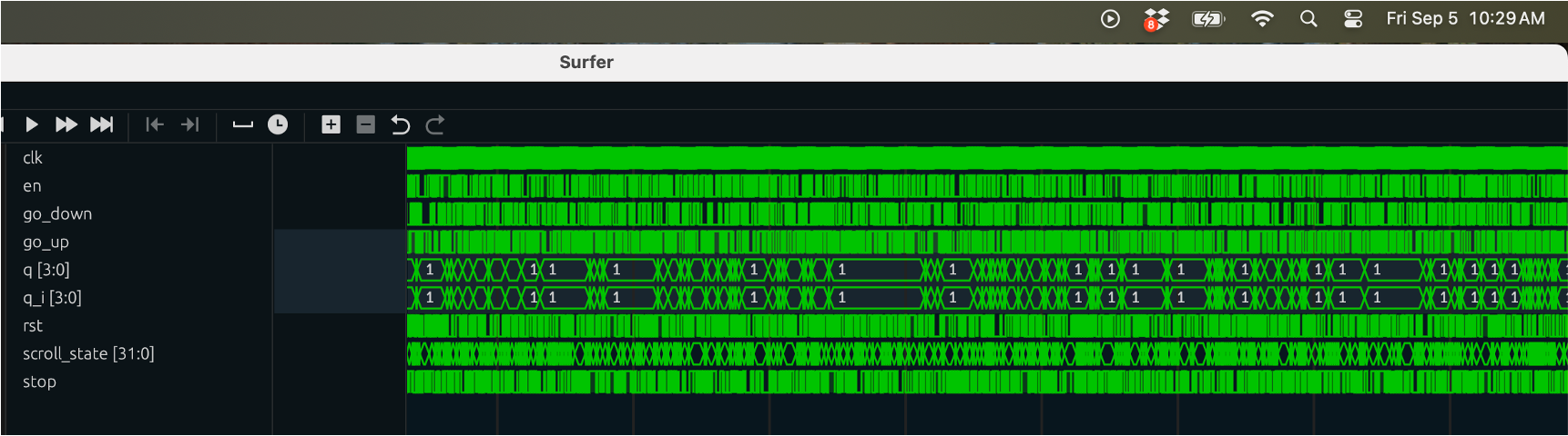
These look cool, but nobody in their right mind would want to analyze it manually so make sure you have an assert check in your test to verify your system state, whatever you call it, and your system output are evolving as they are predicted.
Because I'm a kind person...here's some starter code for a test with some new syntax and patterns you may want to use. Note you'll likely have to import some new things so pay attention to the errors and USE THE COCOTB DOCS.
@cocotb.test()
async def random_walk_test(dut):
    """ Try to randomly walk through state space of led_controller """
    dut._log.info("--->randomly walking")
    rising_clk_edge = RisingEdge(dut.clk)
    falling_clk_edge = FallingEdge(dut.clk)
    read_only = ReadOnly()
    cocotb.start_soon(Clock(dut.clk, 10, units="ns").start(start_high=False))
    await Timer(200, "ns")
    await falling_clk_edge
    dut.stop.value = 0
    dut.go_down.value = 0
    dut.en.value = 0
    dut.rst.value = 1
    await falling_clk_edge
    dut.rst.value = 0
    await Timer(200, "ns")
    dut.go_up.value = 1
    await falling_clk_edge
    dut.go_up.value = 1
    await falling_clk_edge
    dut.en.value = 1
    await rising_clk_edge
    await read_only
    #initial values as they are...
    en = dut.en.value
    rst = dut.rst.value
    stop = dut.stop.value
    go_up = dut.go_up.value
    go_down = dut.go_down.value
    state = state_t(dut.scroll_state.value)
    q = dut.q.value.integer
    # YOU DO: figure out what they should be after upcoming next edge:
    for i in range(5000):
        await rising_clk_edge
        await read_only

        #YOU DO: analyze outputs of dut. Compare to values you predicted...

        await falling_clk_edge
        #YOU DO:
        #   * make signals for upcoming application...
        #   * make prediction about what state/output should be after next rising edge
        #   * apply those signals to dut
When this is all done, and your design is looking solid, upload the entire project here!
hdl and sim folders in the project folder) here.
