Week 05: Linking Stuff Together, IQ
Putting Some Things Together
Please Log In for full access to the web site.
Note that this link will take you to an external site (https://shimmer.mit.edu) to authenticate, and then you will be redirected back to this page.
Overview
What I'd like to do in this lab is explore a little bit of how we can use cocotb's inherent Python nature to rather easily study how modules we build can do signal processing. We're going to feed in a time-series of data to a module (that is built on AXI-streaming), and since we already have gotten some practice putting data on and pulling data out of our device through drivers and monitors, let's go a step further and plot the data.
As a test-case let's use your (hopefully) previously working FIR filter and a little bit of extra stuff.
IQ Demodulation
We talked previously about IQ format. Getting a signal into IQ format can be very useful for processing. When data is captured, on an ADC, for example, it is as a purely real signal in the time domain. If we can convert the signal into a IQ format, that will bring us one step closer to extracting any information that may be encoded in it, including the amplitude of phase.
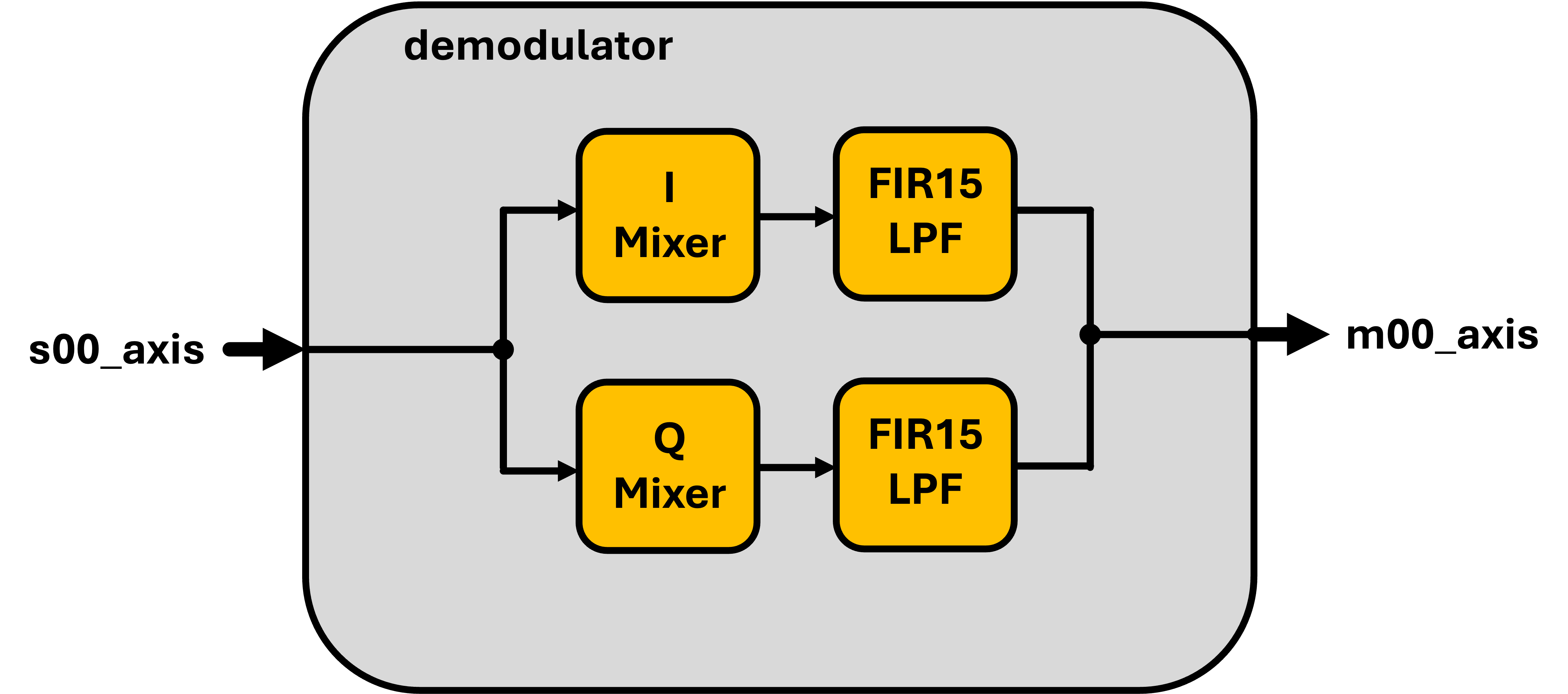
A standard IQ demodulator is shown below. Assuming you know the carrier frequency f_c (which is a big if and takes quite a bit of effort to determine normally), you can create a "local oscillator" or "LO" and create two sine waves, one that we'll call our "I" sinusoid and one that is quadrature with that (90 degrees out of phase) and that we'll call our "Q" sinusoid.
You mix your incoming signal with these two in-quadrature LO signals and the output will be your signal in IQ format, basically a number that can be thought of as a complex representation of your incoming signal's state (a phasor), completely independent of the frequency it was being carried on.

How does this math work?
Well consider our incoming signal
We can assume that \phi(t) and A(t) are encoding information and changing much more slowly than the carrier frequency f_c. This is almost always the case.
If you multiply (aka "mix") this signal with two other signals, \cos\left(f_ct\right) and \sin\left(fct\right), you'll end up with an in-phase signal:
If you dig through your trig identities, you'll find those ones that are called "Ptolemy's Identities" or something. A few of them can give us this handy relationship:
This turns the two mixed equations into things the following:
for the in-phase product and
for the quadrature product.
The first term in both of these expressions varies over time only based off of information-based terms, the second varies over time from both frequency and information-based terms. If we could isolate these signals from eachother we could extract the information. Thankfully the one we don't want is at a much higher frequency. Running it through a decent low-pass filter will do what we need.
And it turns out we already have a low pass filter from a couple weeks ago.
System to Build
Your job is to implement a AXIS-compatible module that will do this for us.
The FIR can be the identical one you've already developed previously.
The mixer also needs to be an AXIS-compatible module that is parameterizable to make either in-phase or in-quadrature LO to multiply with

Wire everything together so things are working.
The splitting of the incoming AXI stuff is relatively trivial (both halves get the same data). The merger at the end should just involve making sure that your final values are each 16 bits and stackign them such that the output data line is 16 bits of in-phase and 16 bits of in-quadrature values. For back-pressure, you can just use one of the Mixer-FIR paths rather than worry about arbitrating between them (normally this would be a somewhat challenging design decision figuring out how to stall two parallel processes properly), but since these two paths are identical and fully-pipelined, we can just assume they'll always be working identically.
For a sine-wave generator, the 16-bit output one shown below should probably do.
`default_nettype none // prevents system from inferring an undeclared logic (good practice)

//Sine Wave Generator
module sine_generator (
  input wire clk_in,
  input wire rst_in, //clock and reset
  input wire step_in, //trigger a phase step (rate at which you run sine generator)
  output logic signed [15:0] amp_out); //output phase in 2's complement
  parameter STEP_FREQ = 100_000_000; //Hz
  parameter FREQUENCY = 10_000_000; //Hz
  parameter PHASE = 90; //degrees
  localparam CLKS_PER_CYCLE = STEP_FREQ/FREQUENCY; //ok to be non integer
  localparam PHASE_INCR = int'(32'hFFFF_FFFF/CLKS_PER_CYCLE);
  localparam PHASE_OFFSET = int'(1.0*PHASE/360*32'hFFFF_FFFF);
  //parameter PHASE_INCR = 32'b1000_0000_0000_0000_0000_0000_0000_0000>>3; //1/16th of 12 khz is 750 Hz
  logic [31:0] phase;
  logic [31:0] lu_phase;
  logic [15:0] amp;
  logic [15:0] amp_pre;
  assign amp_pre = ({~amp[15],amp[14:0]}); //2's comp output (if not scaling)
  assign amp_out = amp_pre; //decrease volume so it isn't too loud!
  sine_lut lut_1(.clk_in(clk_in), .rst_in(rst_in), .phase_in(lu_phase[31:26]), .amp_out(amp));

  always_ff @(posedge clk_in)begin
    lu_phase <= phase + PHASE_OFFSET;
    if (rst_in)begin
      phase <= 32'b0;
    end else if (step_in)begin
      phase <= phase+PHASE_INCR;
    end
  end
endmodule

//6bit sine lookup, 8bit depth
module sine_lut(input wire [5:0] phase_in, input wire clk_in, input wire rst_in, output logic[15:0] amp_out);
  always_ff @(posedge clk_in)begin
    if (rst_in)begin
      amp_out <= 0;
    end else begin
      case(phase_in)
       6'd0: amp_out<=32768;
       6'd1: amp_out<=35979;
       6'd2: amp_out<=39160;
       6'd3: amp_out<=42279;
       6'd4: amp_out<=45307;
       6'd5: amp_out<=48214;
       6'd6: amp_out<=50972;
       6'd7: amp_out<=53555;
       6'd8: amp_out<=55938;
       6'd9: amp_out<=58097;
       6'd10: amp_out<=60013;
       6'd11: amp_out<=61666;
       6'd12: amp_out<=63041;
       6'd13: amp_out<=64124;
       6'd14: amp_out<=64905;
       6'd15: amp_out<=65377;
       6'd16: amp_out<=65535;
       6'd17: amp_out<=65377;
       6'd18: amp_out<=64905;
       6'd19: amp_out<=64124;
       6'd20: amp_out<=63041;
       6'd21: amp_out<=61666;
       6'd22: amp_out<=60013;
       6'd23: amp_out<=58097;
       6'd24: amp_out<=55938;
       6'd25: amp_out<=53555;
       6'd26: amp_out<=50972;
       6'd27: amp_out<=48214;
       6'd28: amp_out<=45307;
       6'd29: amp_out<=42279;
       6'd30: amp_out<=39160;
       6'd31: amp_out<=35979;
       6'd32: amp_out<=32768;
       6'd33: amp_out<=29556;
       6'd34: amp_out<=26375;
       6'd35: amp_out<=23256;
       6'd36: amp_out<=20228;
       6'd37: amp_out<=17321;
       6'd38: amp_out<=14563;
       6'd39: amp_out<=11980;
       6'd40: amp_out<=9597;
       6'd41: amp_out<=7438;
       6'd42: amp_out<=5522;
       6'd43: amp_out<=3869;
       6'd44: amp_out<=2494;
       6'd45: amp_out<=1411;
       6'd46: amp_out<=630;
       6'd47: amp_out<=158;
       6'd48: amp_out<=0;
       6'd49: amp_out<=158;
       6'd50: amp_out<=630;
       6'd51: amp_out<=1411;
       6'd52: amp_out<=2494;
       6'd53: amp_out<=3869;
       6'd54: amp_out<=5522;
       6'd55: amp_out<=7438;
       6'd56: amp_out<=9597;
       6'd57: amp_out<=11980;
       6'd58: amp_out<=14563;
       6'd59: amp_out<=17321;
       6'd60: amp_out<=20228;
       6'd61: amp_out<=23256;
       6'd62: amp_out<=26375;
       6'd63: amp_out<=29556;
     endcase
   end
  end
endmodule
`default_nettype wire
Testing
For testing this system, even if you have a waveform viewer that shows analog signals, you may want to do additional processing on the signal or you may want to plot the signals more nicely.
For example, I fed my system (in cocotb), the following signal:
fs = 100e6 #sampling frequency
n = 1024  #number of samples
T = n*1.0/fs #total time
fc = 10e6 #carrier frequency
cps = 8 #cycles per symbol
sps = fs/fc*cps #samples per symbol
t = np.linspace(0, T, n, endpoint=False) #time vector in seconds
ns = np.linspace(0,fs,n,endpoint=False) #sample vector
phase_noise = np.arange(len(t))/len(t) * 6.28 #phase ranges from 0 to 2pi over the duration
general_noise = np.random.randn(len(t))*0
samples = 500*np.cos(10e6*2*np.pi*t+phase_noise +0) + general_noise
samples = samples.astype(np.int32)
I then fed those samples into the device using the driver infrastructure we developed.
I also modified my monitors to store up all values in an array that I can access.
I also also added a new method to the general idea of the Tester class we were developing last week. Something like this:
    def plot_result(self,length):
      input_vals = self.input_mon.values #array I built up over time (could use for comparing)
      output_vals = np.array(self.output_mon.values)
      top = ((output_vals>>16)&0xFFFF).astype(np.int16)
      bott = (output_vals&0xFFFF).astype(np.int16)
      print(top) #for sanity checking
      print(bott) #for sanity checking
      plot_i_q_time_series(top,bott,length) #some basic matplotlib function I wrote
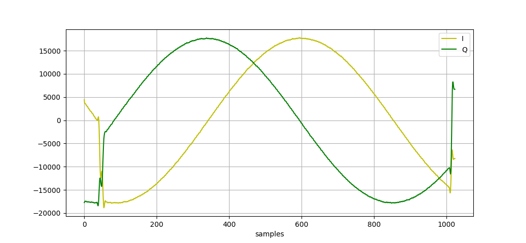
Aside from the start and finish when the FIR is f-ing everythign up, these values actually kinda look like what they should, albeit the actual phase of them might be a little off since the sine waves in the hardware and the ones in python aren't necessarily in-phase.
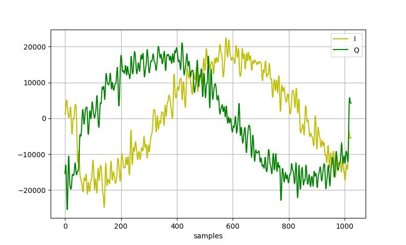
I can add some noise to my sine wave like so:
general_noise = np.random.randn(len(t))*100
Get it working...show that you can, in verilog/hdl, extract the IQ from the incoming signal.
be on the lookout for clipping. in this project.
Put on the Board?
Since I've kinda crunched this week by going back from a Monday-to-Monday schedule to now a Friday-to-Friday, you don't have to put this onto the Pynq board if you don't want. Get (though of course feel free to do so if you do want to!). Instead, make sure it is working in simulation and attach the files below. As we all know, if it works in simulation, it will 100% work in real-life. No doubt, for sure.
