FIR Filter
More Complicated AXI Streaming
Please Log In for full access to the web site.
Note that this link will take you to an external site (https://shimmer.mit.edu) to authenticate, and then you will be redirected back to this page.
Finite Impulse Response Filter
The Finite Impulse Response (FIR) filter is a classic system. Without going into hyperbolics, it is hard to overemphasize how important and versatile it is...I mean it is essentially performing convolution for us. As I said in lecture, it can be used for tons of things.
The math formula for it is pretty easy...the output at any point in time is the sum of a certain number of past values (A finite number of them), each multiplied by the appropriate coefficients. This can readily be envisioned in a digital system:
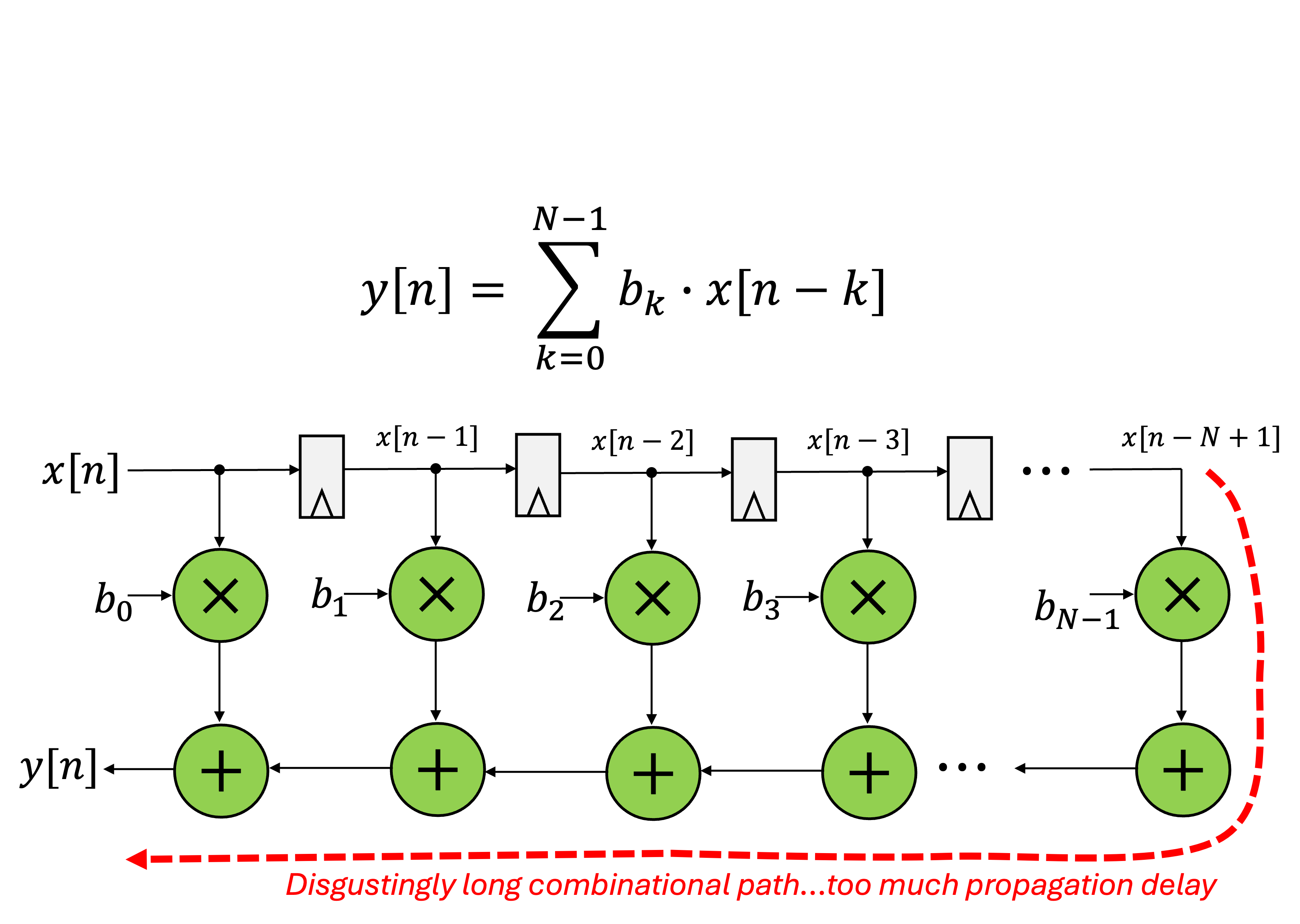
That design has a lot of timing issues, in particular a potentially awful critical path. Refactoring the timing can yield an equivalent design that looks like the following:
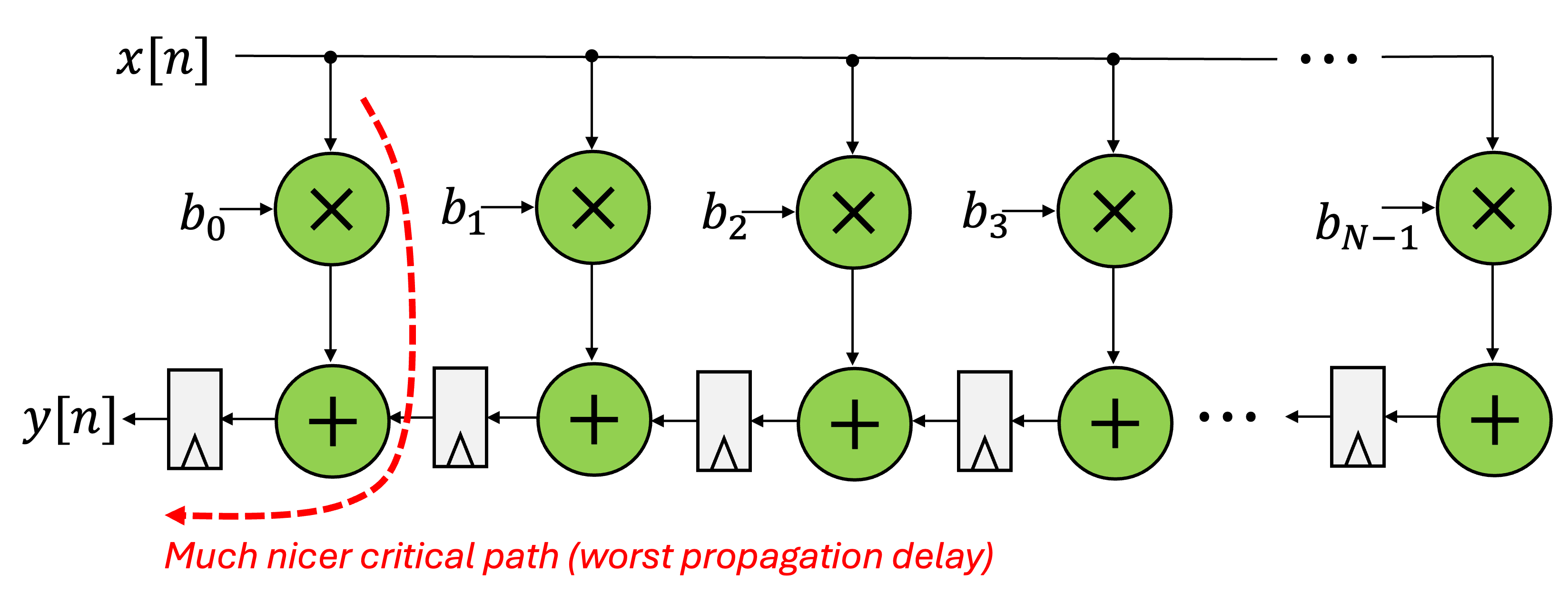
This is what we'll try to design here. Start to think about how this would look in Verilog. Probably some for loops, yeah?
Coefficients
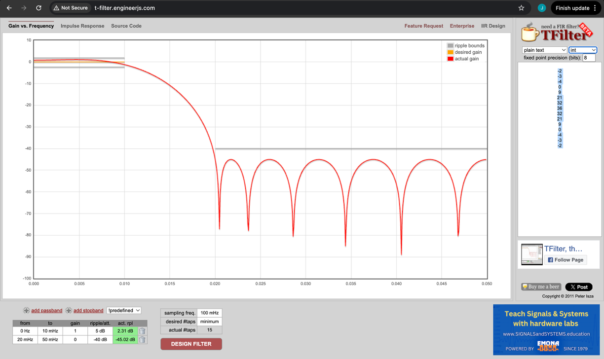
For the purposes of this week, let's design a 15 tap FIR filter with coefficients chosen to give the frequency response shown below:
There is a great tool to design these found here. You can basically tell it the pass bands and stop bands and various levels you want to pass/block at. We'll aim for a pass band out to 10 MHz with the stop band existing from 20 MHz up (at a 100 MHz sample rate). Entering those specs in will give us the following coefficients:
You can also, on that site, see what the impulse response would be too (this may be helpful)
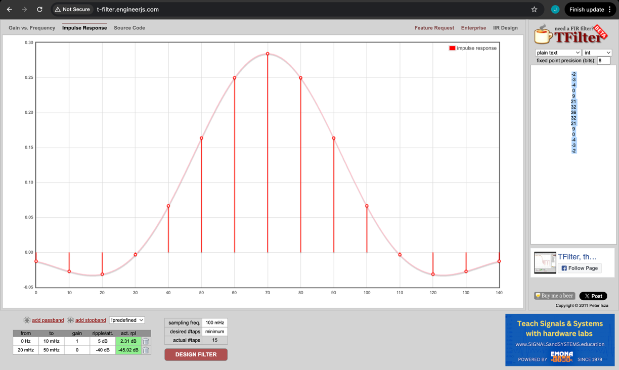
I chose to use the coefficients in their integer form since that is the easiest for us to deploy (avoid floats unless you really need them).
Fitting a FIR into an AXIS Module
We've already gotten some practice testing our simple j_math module with the AXIS standard on the previous page. We'd now like to implement an FIR filter. It'll have exactly the same input and output interfaces (two AXIS channels, one in (slave), one out (master)). However the calculation of an FIR on any given timestep involves a lot more calculations and so requires a carefully laid out design as shown in Figure 1 (and more importantly 2 above).
I hesitate to say this, since I know it can be hard, but in my opinion, the difficulty of designing an AXIS FIR has less to do with the FIR itself (watch your signed math and pipeline your signals appropriately) and more with handling some of the specs of AXIS. In particular:
-
The previous design
j_mathwas a stateless calculation. On any given timestep,3*x+10000was calculated given the input and that was it. This lack of state allowed us to implement what is effectively a pass-through like system that obeys AXIS rules simply because it is doing whatever the master driving it and slave receiving from it tell it. Assuming they're in standard, then you'll be in standard. -
In the case of the FIR, the calculation on any given time step is based on past inputs. It is stateful and that poses a number of challenges:
- Handling the starting and stopping of data is important. You can just pass invalid data through the system. It needs to be ignored and you need to stall your entire pipeline out for it to preserve its state. The progress of your stateful behavior must be based on the appearance of valid/ready data at the input.
- Handling stalls from the consumer/slave device (your M port). If downstream is not prepared to receive data you need to stop the updating and tell your upstream partner to also stop immediately!
- Handling
TLASTcan be a pain. This arises from the fact that when aTLASTsignal appears at your input port there may very well be no data left to get fed in, but you machine needs to know to keep running its calculations until it produces a TLAST value at its output.
In the case of convolution this arises because of the slip-n-slide nature of how it behaves. When the last bit of data is introduced into the filter, we still need to give it time to propagate through all the taps (during that time we shoudl feed 0's into the input).
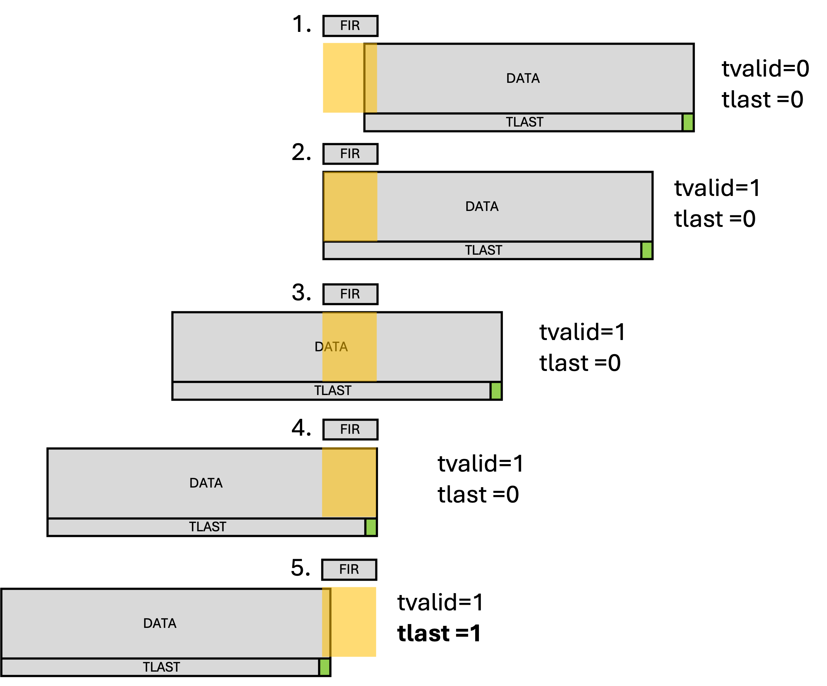
This is a "classic" problem in convolution. No matter what, you have to choose a side to pad with fake data to ensure the result of your convolution is the same length as your original data. You could equally argue that the first time a VALID data comes in your put a VALID out, but I'd like you to do the way shown in the figure mainly because it forces the issue of buffer flushing. In many systems that are stateful, you'll run into the situation
In normal operation, your system should only "increment one step" if it sees valid data on its input (And told the input that it was ready). Otherwise it should stall out. However if it sees data accompanied by a TLAST and then sees no more, it shouldn't stall out...it'll do that potentially forever (and failure to avoid this will cause the DMA to time out waiting for an amount of data that never comes. Instead it should use teh fact that it has seen a TLAST signal to "flush its buffers" to make sure the last N calculations are completed so that it can itself send out a TLAST.
To help you get started, I'm giving you a bit of stuff to take care of the coefficients setup. You can do this more extensibly by readmemh, but making that work in both cocotb and Vivado is annoying so we'll just hardcode the values for now (and hardcode the tap count at 15 rather than parameterize it to hell...these could be things you fix in future implementations).
Other than the wrapper and coefficients, the rest of the design is up to you...
module fir_15 #
  (
    parameter integer C_S00_AXIS_TDATA_WIDTH  = 32,
    parameter integer C_M00_AXIS_TDATA_WIDTH  = 32
  )
  (
  // Ports of Axi Slave Bus Interface S00_AXIS
  input wire  s00_axis_aclk, s00_axis_aresetn,
  input wire  s00_axis_tlast, s00_axis_tvalid,
  input wire [C_S00_AXIS_TDATA_WIDTH-1 : 0] s00_axis_tdata,
  input wire [(C_S00_AXIS_TDATA_WIDTH/8)-1: 0] s00_axis_tstrb,
  output logic  s00_axis_tready,

  // Ports of Axi Master Bus Interface M00_AXIS
  input wire  m00_axis_aclk, m00_axis_aresetn,
  input wire  m00_axis_tready,
  output logic  m00_axis_tvalid, m00_axis_tlast,
  output logic [C_M00_AXIS_TDATA_WIDTH-1 : 0] m00_axis_tdata,
  output logic [(C_M00_AXIS_TDATA_WIDTH/8)-1: 0] m00_axis_tstrb
  );

  localparam NUM_COEFFS = 15;
  logic signed [7:0] coeffs [NUM_COEFFS-1 : 0];
  //initializing values
  initial begin //updated you coefficients
    coeffs[0] = 0;
    coeffs[1] = 0;
    coeffs[2] = 0;
    coeffs[3] = 0;
    coeffs[4] = 0;
    coeffs[5] = 0;
    coeffs[6] = 0;
    coeffs[7] = 0;
    coeffs[8] = 0;
    coeffs[9] = 0;
    coeffs[10] = 0;
    coeffs[11] = 0;
    coeffs[12] = 0;
    coeffs[13] = 0;
    coeffs[14] = 0;
    for(int i=0; i<NUM_COEFFS; i++)begin
      intmdt_term[i] = 0;
    end
    $display("DONE!");
  end

endmodule
Verification and TLAST
On the previous page you already built up some driver and monitor infrastructure to poke at this system. In particular, you need to make sure that given the set of data you drove into on the previous page. Honestly, that testbench is probably pretty good to use for this one.
Feel free to use it. Remember we want to not only worry about getting the right values, but also making sure we are sending at our output the correct number of values and that the TLAST is getting propagated forward. Use the monitor readout to validate the one thing count and presence of LAST signals (And the waveform). For validating the actual FIR values, I think you'll be fine to just look at the values by eye...consider some of the impule responses present in the input data...they should match the coefficients (a characteristic response of an FIR to an impulse response).
Good luck.
fir15.sv and testbench here!
