AXIS Interface
Talking to AXIS
Please Log In for full access to the web site.
Note that this link will take you to an external site (https://shimmer.mit.edu) to authenticate, and then you will be redirected back to this page.
A Generic AXIS Module
For this week we want to build a couple of AXI Streaming (AXIS) modules. One we'll basically give to you, and the second, more difficult one, you'll build. As we've talked about in class, AXI Streaming is part of the AMBA/AXI4 specification. It is the simplest of the three classes (AXI Full, AXI-Lite, and AXI Streaming). This simplicity comes from the fact that:
- Only Data is moved around: There are not official address channels, response channels, etc... you just move data.
- Transactions occur unidirectionally: Data only moves from Master to Slave device. There is no backwards movement.
- It can be very high throughput. Since everything in an AXI Stream is moving data in the same direction, it can be very amenable to high-throughput "stream" processing.
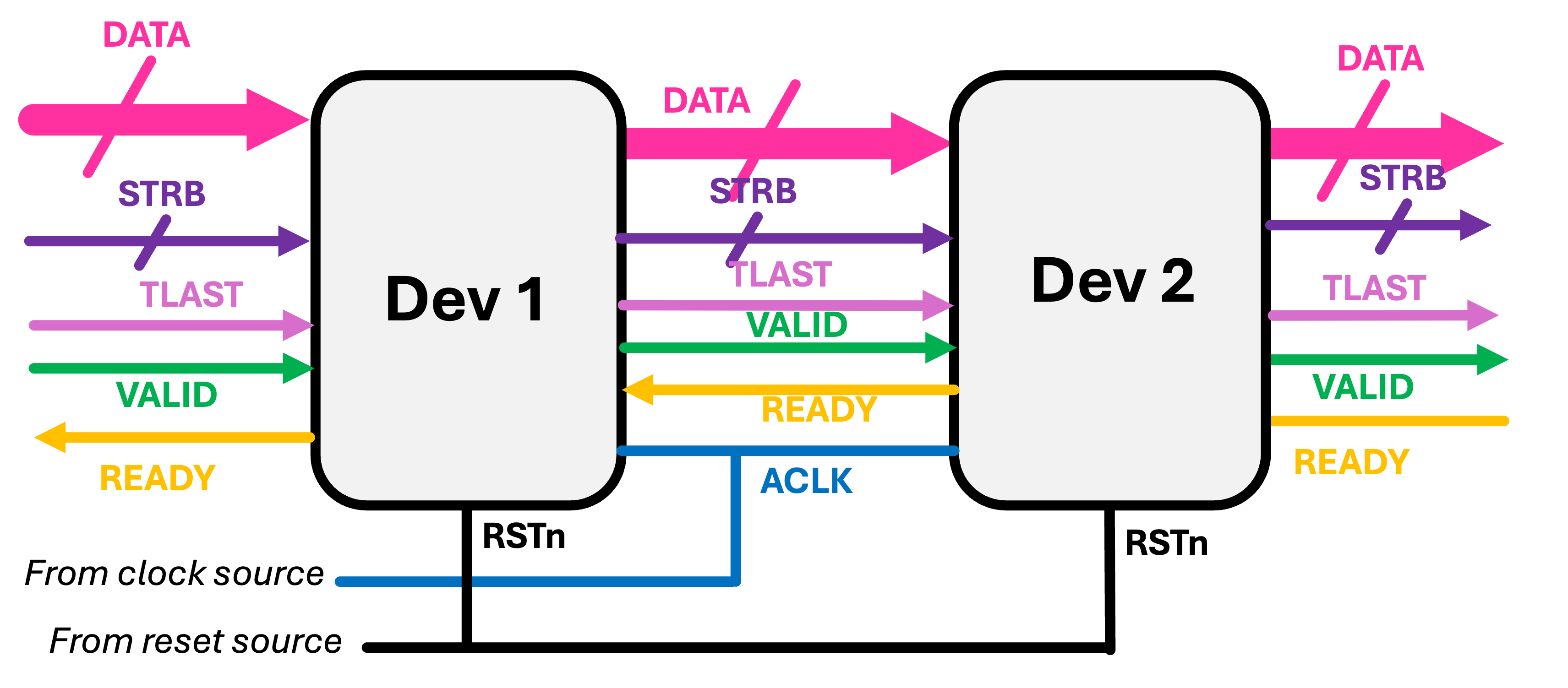
When it comes time to write an AXIS module, we'll worry about the following sets of signals on a bus:
axis_aclk: The clock of the channel. Data is sampled on the rising edge of this clock.axis_aresetn: The reset of the channel (active low). Both parties should reset during this signalaxis_tdata [31:0]: The payload of the channel. This is 32 bits (standard) of data. It can be used for whatever you want/interpretted in any way so desired (int,float, char, custom, whatever)...but this is the stuff getting moved around and what it is all for.axis_tvalid: The signal that a producer/master indicates it has valid data.axis_tready: The signal that a consumer/slave indicates that it is ready for data.axis_tstrb[3:0]: A signal that can be used to indicate which of the bytes in the data are valid/to be used. Can be set to4'b1111by default.axis_tlast: A signal indicating that the data on that clock cycle is the "last" of that set. This is useful in indicating the end of a data burst or packet. Often times final-endpoint consuming devices will be looking forTLASTsignasl to know when to stop trying to read.
All signals propagate downstream with the notable exception of ready which propagates upstream and is a form of backpressure, allowing downstream devices to pause the pipeline and avoid data loss. Ideally, ready will propagate upstream quickly to avoid data collisions within/between modules (think of a bunch of cars driving in a line and the first one brakes...it is often the fact that cars further back don't know of the braking that causes an accident. If they'd all know that the first just applied brakes they could do the same.)
A basic AXIS module in Verilog is shown below:
module general_wrapper #
	(
		parameter integer C_S00_AXIS_TDATA_WIDTH	= 32,
		parameter integer C_M00_AXIS_TDATA_WIDTH	= 32,
	)
	(
		// Ports of Axi Slave Bus Interface S00_AXIS
		input wire  s00_axis_aclk, s00_axis_aresetn,
		input wire  s00_axis_tlast, s00_axis_tvalid,
		input wire [C_S00_AXIS_TDATA_WIDTH-1 : 0] s00_axis_tdata,
		input wire [(C_S00_AXIS_TDATA_WIDTH/8)-1: 0] s00_axis_tstrb,
		output logic  s00_axis_tready,

		// Ports of Axi Master Bus Interface M00_AXIS
		input wire  m00_axis_aclk, m00_axis_aresetn,
		input wire  m00_axis_tready,
		output logic  m00_axis_tvalid, m00_axis_tlast,
		output logic [C_M00_AXIS_TDATA_WIDTH-1 : 0] m00_axis_tdata,
		output logic [(C_M00_AXIS_TDATA_WIDTH/8)-1: 0] m00_axis_tstrb
	);

endmodule
The simplest thing you could do with from this would be to make an AXIS "wire"...a completely useless passthrough object. This wouldn't do anything, but it at least shows your minimum viable AXIS.
module axis_wire #
	(
		parameter integer C_S00_AXIS_TDATA_WIDTH	= 32,
		parameter integer C_M00_AXIS_TDATA_WIDTH	= 32,
	)
	(
		// Ports of Axi Slave Bus Interface S00_AXIS
		input wire  s00_axis_aclk, s00_axis_aresetn,
		input wire  s00_axis_tlast, s00_axis_tvalid,
		input wire [C_S00_AXIS_TDATA_WIDTH-1 : 0] s00_axis_tdata,
		input wire [(C_S00_AXIS_TDATA_WIDTH/8)-1: 0] s00_axis_tstrb,
		output logic  s00_axis_tready,

		// Ports of Axi Master Bus Interface M00_AXIS
		input wire  m00_axis_aclk, m00_axis_aresetn,
		input wire  m00_axis_tready,
		output logic  m00_axis_tvalid, m00_axis_tlast,
		output logic [C_M00_AXIS_TDATA_WIDTH-1 : 0] m00_axis_tdata,
		output logic [(C_M00_AXIS_TDATA_WIDTH/8)-1: 0] m00_axis_tstrb
	);

  assign m00_axis_tdata = s00_axis_tdata; //these all going downstream
  assign m00_axis_tvalid = s00_axis_tvalid;
  assign m00_axis_tlast = s00_axis_tlast;
  assign m00_axis_tstrb = s00_axis_tstrb;
  assign s00_axis_tready = m00_axis_tready; //going upstream
endmodule
The whole point of this framework is to do something, however, so let's see an example of an AXIS module that actually does something.
Here's a module, called j_math that takes in a number x and calculates 3\cdot x + 10000. It does it using one layer of flip flops. Note in lecture I displayed it with two layers. I decided to go with one for this after all.
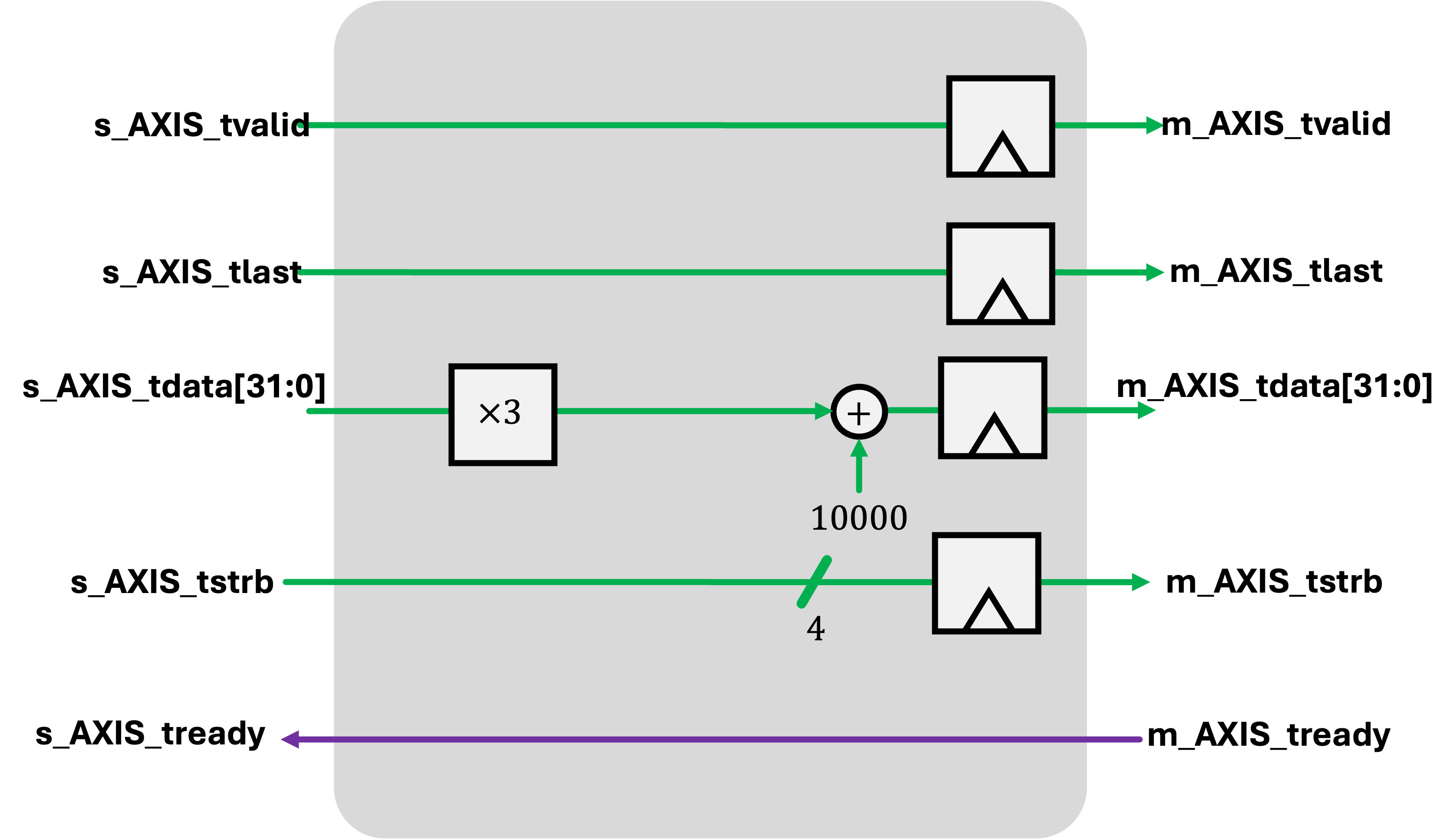
Notice all the with-data signals are pipelined appropriately to ensure that the metadata keeps up with the signals.
module j_math #
	(
		parameter integer C_S00_AXIS_TDATA_WIDTH	= 32,
		parameter integer C_M00_AXIS_TDATA_WIDTH	= 32
	)
	(
		// Ports of Axi Slave Bus Interface S00_AXIS
		input wire  s00_axis_aclk, s00_axis_aresetn,
		input wire  s00_axis_tlast, s00_axis_tvalid,
		input wire [C_S00_AXIS_TDATA_WIDTH-1 : 0] s00_axis_tdata,
		input wire [(C_S00_AXIS_TDATA_WIDTH/8)-1: 0] s00_axis_tstrb,
		output logic  s00_axis_tready,

		// Ports of Axi Master Bus Interface M00_AXIS
		input wire  m00_axis_aclk, m00_axis_aresetn,
		input wire  m00_axis_tready,
		output logic  m00_axis_tvalid, m00_axis_tlast,
		output logic [C_M00_AXIS_TDATA_WIDTH-1 : 0] m00_axis_tdata,
		output logic [(C_M00_AXIS_TDATA_WIDTH/8)-1: 0] m00_axis_tstrb
	);

  logic m00_axis_tvalid_reg, m00_axis_tlast_reg;
  logic [C_M00_AXIS_TDATA_WIDTH-1 : 0] m00_axis_tdata_reg;
  logic [(C_M00_AXIS_TDATA_WIDTH/8)-1: 0] m00_axis_tstrb_reg;

  assign m00_axis_tvalid = m00_axis_tvalid_reg;
  assign m00_axis_tlast = m00_axis_tlast_reg;
  assign m00_axis_tdata = m00_axis_tdata_reg;
  assign m00_axis_tstrb = m00_axis_tstrb_reg;
  assign s00_axis_tready = m00_axis_tready;

  always_ff @(posedge s00_axis_aclk)begin
    if (s00_axis_aresetn==0)begin
      m00_axis_tvalid_reg <= 0;
      m00_axis_tlast_reg <= 0;
      m00_axis_tdata_reg <= 0;
      m00_axis_tstrb_reg <= 0;
    end else begin
      m00_axis_tvalid_reg <= s00_axis_tvalid;
      m00_axis_tlast_reg <= s00_axis_tlast;
      m00_axis_tdata_reg <=3*s00_axis_tdata+10000;
      m00_axis_tstrb_reg <= s00_axis_tstrb;
    end
  end
endmodule
This module implementation does have one flaw, however, and we'll explore it a bit as we go through this page.
Cocotb Bus
OK now we want to testbench this stuff but as our systems get more and more complex, it is going to get harder and harder to try to poke at stuff and remember what we wanted to get and so on. You already will kinda know what I mean just from having written testbenches in the past. They can get nasty.
One step toward keeping this mess under control is to be able to just easily throw stuff at the input of a device using high-level commands. And also have a device that can listen to what goes in and out and can provide some level of interpretation to what is happening at a level more readable than us just counting clock cycles.
Towards this end we're going to develop a monitor and a driver for our AXIS Bus, two core elements in a modern testing framework (see lecture 05).
AXIS Monitor
Go and install cocotb_bus. You can do this by doing pip install cocotb_bus. Create a new cocotb file (you can base it off of your SPI testbenches from last week). Update the names and things as needed, of course.
Bring in the following libraries at the top:
from cocotb_bus.bus import Bus
from cocotb_bus.drivers import BusDriver
from cocotb_bus.monitors import Monitor
from cocotb_bus.monitors import BusMonitor
import numpy as np
Now cocotb_bus has a few very useful constructs in it as we mentioned in class.
One of them is Bus, which is a Python class that groups a set of signals. We'll not use Buses on their own much but we will use they for the core part of several other devices. The first is the Bus Monitor.
The BusMonitor is a device that is attached to a bus and then upon creation starts running and monitoring the bus. While monitoring, it can look for particular types of signals and then carry out task like reporting and logging them when they see relevant things appear. You'll rarely use the BusMonitor class on its own, you'll instead make customized versions of the class using class inheritance like Python allows you to do.
An example of a BusMonitor implementation is shown below. I wrote it to basically "Monitor" an AXIS bus and report what it sees. Using the rules of AXI Streaming, (most importantly, when ready and valid are high on a rising edge, a exchange has taken place, the system keeps track of the number of transactions it has observed as well as attributes of them. Eventually we'll want to send them off to a special spot (self._recv which can trigger callbacks and things...we'll talk about in the future), but for now we'll just have it print what it sees!
class AXISMonitor(BusMonitor):
    """
    monitors axi streaming bus
    """
    transactions = 0
    def __init__(self, dut, name, clk):
        self._signals = ['axis_tvalid','axis_tready','axis_tlast','axis_tdata','axis_tstrb']
        BusMonitor.__init__(self, dut, name, clk)
        self.clock = clk
        self.transactions = 0
    async def _monitor_recv(self):
        """
        Monitor receiver
        """
        rising_edge = RisingEdge(self.clock) # make these coroutines once and reuse
        falling_edge = FallingEdge(self.clock)
        read_only = ReadOnly() #This is
        while True:
            await rising_edge
            await falling_edge #sometimes see in AXI shit
            await read_only  #readonly (the postline)
            valid = self.bus.axis_tvalid.value
            ready = self.bus.axis_tready.value
            last = self.bus.axis_tlast.value
            data = self.bus.axis_tdata.value
            if valid and ready:
              self.transactions += 1
              thing = dict(data=data,last=last,name=self.name,count=self.transactions)
              print(thing)
              self._recv(thing)
I wrote this monitor with reusability in mind. Because both the input and output of our streaming modules use the AXIS protocol, we shoudl hopefully be able to apply it to both sides. In fact, some aspects of the BusMonitor class are intentionally designed to allow for this. For example, the annoying naming convention of the Master and Slave Busses atually does have a usage here. We can create two instances of this AXISMonitor like so:
    inm = AXISMonitor(dut,'s00',dut.s00_axis_aclk)
    outm = AXISMonitor(dut,'m00',dut.s00_axis_aclk)
and if you dig through the source code, you'll see that the internal signals we specified as existing on our bus (such as axis_tdata are attached with an _ to the name of the bus s00 or m00, allowing the general name to refer to the specific instance with no problem.
Once you've set/initialized the two bus monitors (one on the input, one on the output), they'll run in the background monitoring the line and reporting (via prints) when they see something.
Deploying them in the test is very easy:
@cocotb.test()
async def test_a(dut):
    """cocotb test for seven segment controller"""
    inm = AXISMonitor(dut,'s00',dut.s00_axis_aclk)
    outm = AXISMonitor(dut,'m00',dut.s00_axis_aclk)
    cocotb.start_soon(Clock(dut.s00_axis_aclk, 10, units="ns").start())
    dut.m00_axis_tready.value = 1
AXIS Driver
The second part we want to develop (And I'm not going to give it to you this time sorry), is the AXISDriver. Specifically this would perform the Master duties on an AXIS channel.
class AXISDriver(BusDriver):
  def __init__(self, dut, name, clk):
    self._signals = ['axis_tvalid', 'axis_tready', 'axis_tlast', 'axis_tdata','axis_tstrb']
    BusDriver.__init__(self, dut, name, clk)
    self.clock = clk
    self.bus.axis_tdata.value = 0
    self.bus.axis_tstrb.value = 0
    self.bus.axis_tlast.value = 0
    self.bus.axis_tvalid.value = 0

  async def _driver_send(self, value, sync=True):
    #you finish
    pass
This is another class that is very rarely used as it is, but is instead used as a prototype for more specific variants. Here the AXISDriver class has all the signals of the AXIS bus in it. At initialization I set the ones that are the Master responsibility to 0.
The async def _driver_send module is what we want to focus on. This function should really not be called directly, instead we'll feed inputs to the class via a different mechanism. These values get placed in a queue like object and executed by _driver_send in order as they get processed.
What value needs to be is left completely open and this is where we can start specify transactions at a very high level. We do not want to be manually specifying which bits are going high with these instructions. We instead want to describe what type of transaction and have _driver_send know how to interpret and implement it.
Two Types of Transfers
We'll come up with a simple framework of two types of transactions:
For our value, design _driver_send to take in a dictionary which has the following two keys:
'type': which is eithersingleorburst'contents': which has data specific for the type of transfer.
A single value will involve setting the specified value of data, last, and strb as well as turn valid to 1 on the falling edge of the AXI Clock, and ensure that ready is asserted by the slave/consumer (if it isn't it should wait until it is). Once a ready=1 signal has been seen, the valid is dropped to 0 on the following falling edge. Along with this, though the module should only. The result of running multiple single transations back to back will be the valid signal cycling high and low every other clock cycle.
The other type of transaction is burst. This one takes in an array of values and holds feeds them onto the line one at a time continuously, never deasserting valid and finally asserting a TLAST signal on the final point of data. While doing this, it should also pay attention to ready from the slave and pause/hold on adding new values until things are ready again.
Two examples of transactions we'd want to work with are shown below:
{"type":"single", "contents": {"data":5, "last":0, "strb":15}}
{"type":"burst", "contents": {"data": np.array(9*[0]+[1]+30*[0]+[-2]+59*[0])}}
In deployment, their use would look like tie following:
    for i in range(50):
      data = {'type':'single', "contents":{"data": random.randint(1,255),"last":0,"strb":15}}
      ind.append(data)
    data = {'type':'burst', "contents":{"data": np.array(list(range(100)))}}
    ind.append(data)
So build your AXISDriver. With the version of j_math provided, if you run the test below you should end up with a readout that ends with something like:
{'data': 00000000000000000000000001100010, 'last': 0, 'name': 's00', 'count': 149, 'time': 2005000}
{'data': 00000000000000000010100000110011, 'last': 0, 'name': 'm00', 'count': 148, 'time': 2005000}
{'data': 00000000000000000000000001100011, 'last': 1, 'name': 's00', 'count': 150, 'time': 2015000}
{'data': 00000000000000000010100000110110, 'last': 0, 'name': 'm00', 'count': 149, 'time': 2015000}
{'data': 00000000000000000010100000111001, 'last': 1, 'name': 'm00', 'count': 150, 'time': 2025000}
  5020.00ns INFO     cocotb.regression                  test_a passed
and an fst file like this.
@cocotb.test()
async def test_a(dut):
    """cocotb test for seven segment controller"""
    inm = AXISMonitor(dut,'s00',dut.s00_axis_aclk)
    outm = AXISMonitor(dut,'m00',dut.s00_axis_aclk)
    ind = AXISDriver(dut,'s00',dut.s00_axis_aclk)
    cocotb.start_soon(Clock(dut.s00_axis_aclk, 10, units="ns").start())
    await set_ready(dut,1) # you should write
    await reset(dut.s00_axis_aclk, dut.s00_axis_aresetn,2,0) # you should write
    #feed the driver:
    for i in range(50):
      data = {'type':'single', "contents":{"data": random.randint(1,255),"last":0,"strb":15}}
      ind.append(data)
    data = {'type':'burst', "contents":{"data": np.array(list(range(100)))}}
    ind.append(data)
    await ClockCycles(dut.s00_axis_aclk, 500)
    assert inm.transactions==outm.transactions, f"Transaction Count doesn't match! :/"
Put in some back pressure.
Now let's modify the test a bit. Instead of letting the READY signal on the downstream slave sit at 1. Let's turn it on and off a bit. It should have every right to do so and the modules we have should be able to react to it appropriately.
@cocotb.test()
async def test_a(dut):
    """cocotb test for seven segment controller"""
    inm = AXISMonitor(dut,'s00',dut.s00_axis_aclk)
    outm = AXISMonitor(dut,'m00',dut.s00_axis_aclk)
    ind = AXISDriver(dut,'s00',dut.s00_axis_aclk)
    cocotb.start_soon(Clock(dut.s00_axis_aclk, 10, units="ns").start())
    await set_ready(dut,1)
    await reset(dut.s00_axis_aclk, dut.s00_axis_aresetn,2,0)
    #feed the driver:
    for i in range(50):
      data = {'type':'single', "contents":{"data": random.randint(1,255),"last":0,"strb":15}}
      ind.append(data)
    #data = {'type':'burst', "contents":{"data": np.array(20*[0]+[1]+30*[0]+[-2]+59*[0])}}
    data = {'type':'burst', "contents":{"data": np.array(list(range(100)))}}
    ind.append(data)
    #new below this:
    await ClockCycles(dut.s00_axis_aclk, 50)
    await set_ready(dut,0)
    await ClockCycles(dut.s00_axis_aclk, 300)
    await set_ready(dut,1)
    await ClockCycles(dut.s00_axis_aclk, 10)
    await set_ready(dut,0)
    await ClockCycles(dut.s00_axis_aclk, 10)
    await set_ready(dut,1)
    await ClockCycles(dut.s00_axis_aclk, 300)
    assert inm.transactions==outm.transactions, f"Transaction Count doesn't match! :/"
Running this with the j_math we provided will result in a different report from the monitors:
{'data': 00000000000000000010100000110011, 'last': 0, 'name': 'm00', 'count': 150, 'time': 5105000}
{'data': 00000000000000000000000001100011, 'last': 1, 'name': 's00', 'count': 150, 'time': 5115000}
{'data': 00000000000000000010100000110110, 'last': 0, 'name': 'm00', 'count': 151, 'time': 5115000}
{'data': 00000000000000000010100000111001, 'last': 1, 'name': 'm00', 'count': 152, 'time': 5125000}
  6720.00ns INFO     cocotb.regression                  test_a failed
Shoot it looks like we're duplicating packets somehow. The input and output monitors are seeing different counts. This is no good.
Fix J_math
Now 99% of the time the simple implementation of j_math is probably fine. Putting on/off some backpressure, reveals some opportunities for double-counting beats of data. We need to fix this. Thankfully this should be pretty easy.
We are violating AXI protocol on our output by constantly feeding values through. If the ready on the downstream device gets deasserted, we still move data through an that's a problem. Instead we should stop our pipeline if ready goes low. A simple change like shown below can take care of that.
module j_math #
	(
		parameter integer C_S00_AXIS_TDATA_WIDTH	= 32,
		parameter integer C_M00_AXIS_TDATA_WIDTH	= 32
	)
	(
		// Ports of Axi Slave Bus Interface S00_AXIS
		input wire  s00_axis_aclk, s00_axis_aresetn,
		input wire  s00_axis_tlast, s00_axis_tvalid,
		input wire [C_S00_AXIS_TDATA_WIDTH-1 : 0] s00_axis_tdata,
		input wire [(C_S00_AXIS_TDATA_WIDTH/8)-1: 0] s00_axis_tstrb,
		output logic  s00_axis_tready,

		// Ports of Axi Master Bus Interface M00_AXIS
		input wire  m00_axis_aclk, m00_axis_aresetn,
		input wire  m00_axis_tready,
		output logic  m00_axis_tvalid, m00_axis_tlast,
		output logic [C_M00_AXIS_TDATA_WIDTH-1 : 0] m00_axis_tdata,
		output logic [(C_M00_AXIS_TDATA_WIDTH/8)-1: 0] m00_axis_tstrb
	);

  logic m00_axis_tvalid_reg, m00_axis_tlast_reg;
  logic [C_M00_AXIS_TDATA_WIDTH-1 : 0] m00_axis_tdata_reg;
  logic [(C_M00_AXIS_TDATA_WIDTH/8)-1: 0] m00_axis_tstrb_reg;

  assign m00_axis_tvalid = m00_axis_tvalid_reg;
  assign m00_axis_tlast = m00_axis_tlast_reg;
  assign m00_axis_tdata = m00_axis_tdata_reg;
  assign m00_axis_tstrb = m00_axis_tstrb_reg;
  //change...only if there is a slot for new data to go into:
  //this should avoid deadlock.
  assign s00_axis_tready = m00_axis_tready || ~m00_axis_tvalid;

  always_ff @(posedge s00_axis_aclk)begin
    if (s00_axis_aresetn==0)begin
      m00_axis_tvalid_reg <= 0;
      m00_axis_tlast_reg <= 0;
      m00_axis_tdata_reg <= 0;
      m00_axis_tstrb_reg <= 0;
    end else begin
      //only if there is room in either our registers...
      //or downstream consumer/slave do we update.
      if (s00_axis_tready)begin
        m00_axis_tvalid_reg <= s00_axis_tvalid;
        m00_axis_tlast_reg <= s00_axis_tlast;
        m00_axis_tdata_reg <=3*s00_axis_tdata+10000;
        m00_axis_tstrb_reg <= s00_axis_tstrb;
      end
    end
  end
endmodule
This is closer to what we want. Only when the downstream slave/consumer device is ready to receive data do we even update our own system. This will take care of the double-beats that might appear on assertion/deassertion edges of READY.
If you run the test again, you should basically get an equal number of in/out packets on the line.
