SPI Model
Making a Friend for our SPI Verilog
Please Log In for full access to the web site.
Note that this link will take you to an external site (https://shimmer.mit.edu) to authenticate, and then you will be redirected back to this page.
The SPI TX module you wrote previously is lonely. Nobody understands it. Its whole job is to talk to another device, but it has no one to talk to! Let's write a python implementation that can play with it and be used for verification.
You're making another cocotb testbench! Certain context pieces of the testbench can be copied exactly from last week's testbench: get started by making a new testbench file, test_spi_tx.py; copy over the imports and the runner code (the counter_runner() function, though perhaps you want to rename it..); modify the runner function to name the correct verilog sources, HDL toplevel modules, and python test modules for the code you're testing this week. This boilerplate will remain largely unchanged, aside from file sources/module names, for all the cocotb testbenches you write.
As you write cocotb code, there's an amazing reference card you can use to ensure you're using proper syntax for things! It's great, I'd strongly recommend using it.
Simulation Models: a new way to test
So far, most of the testbenches you've likely written (either in SystemVerilog back in 6.205, or in the cocotb testbench last week) can basically be boiled down to "wait a fixed amount of time, then change some input values, so you can look at the waveform of the output values." This will get you somewhere, but it quickly gets really unwieldy.
Now that we're in the land of Python, we don't have to write these rudimentary testbenches anymore; we can instead write functions that actually intelligently use our design's inputs and outputs the same way we would in a higher level testbench. We can even go so far as to have a coroutine function that we start running in the background, and then continually simulates what device we might connect to our design would do in response to the signals our DUT produces. If we make an accurate enough model coroutine to represent the device we'll be connecting our design to on hardware, we can make ourselves far more confident that once we leave simulation we'll successfully interact with our devices! If we do it right, we'll have a set of reusable functions that let our high-level tests read like high-level commands rather than being buried in endless hard-to-comprehend assign statements and wait statements.
Here, we'll guide you through what each component of your model functions should be accomplishing so as to accurately represent the devices that connect to our spi_tx module. It'll be your job to translate the behavior into cocotb Python code and have them run within your cocotb tests.1
Async functions and cocotb
Cocotb is a Python library that relies heavily on asynchronous functions! By writing asynchronous functions, we're able to launch tasks in the background that keep operating as we carry out our default test function, and thus be able to manage several tasks in parallel! We won't go into all of the details of how asynchronous functions work within python, but the most core component to keep in mind is that: each time you await another function call, you yield to other processes that are scheduled to also be happening (who may have awaited something else previously!). By awaiting events, the interpreter is freed to go alternate to another "simultaneous" task.
Specifically within cocotb, many of the functions we await for are triggers, which fire at speicifc simulation steps as functions continue onwards. Since all of the coroutines we have will await for simulation timesteps, they can all run "in parallel" as the simulation steps pass by.
In order to properly ensure that Python can do its coroutine managing, make sure that any function that awaits for a trigger is declared with the keyword async in the signature, like so:
async def foo(a,b):
And in order to access many of the cocotb triggers that let functions interact with timestep changes, make sure to include an import statement like the following (you might only need some of the triggers, feel free to customize your import statement as needed)
from cocotb.triggers import Timer, ClockCycles, RisingEdge, FallingEdge, ReadOnly,with_timeout, First, Join
Driving a value into our dut
As a first foray into writing a function for our cocotb test, lets wrap together all the behavior necessary to throw a value into data_in! If we were using our spi_tx module in a larger design, there are rules to how we should send in data in: we need to wait until busy_out is held low, indicating the module is ready to be used, and on the rising clock edge when data is passed in, trigger_in should be high.
That's all behavior that we can wrap up into a function! If we do it right, then within our tests we'll be able to await drive_data_in(dut,value), and know that after this line executes, our module will be up and running with the data we just sent in.
Try your hand at making a function async def drive_data_in(dut,value) which safely transmits a message into our module. It should:
- Repeatedly
awaitforRisingEdges of the system clock, and check whetherbusy_outis low. Don't proceed until the module is not busy. - Set
trigger_inhigh, anddata_into be equal to the value passed to our function - Wait one clock cycle
await ClockCycles(dut.clk_in,1),and settrigger_inlow again.
Driving reset
A similar function can be written to drive a value to our reset wire, except it's even simpler! Just set reset high, await a couple clock cyles, and then set reset low again. It's not a necessary function in any way, but this is a block of code you'll find yourself writing a ton, so if its packaged up into a function to grab then your life becomes easier!
Write a function async def reset(rst_wire) to drive a reset value for a couple clock cycles; it can then be called with await reset(dut.rst_in).
Modeling our SPI device
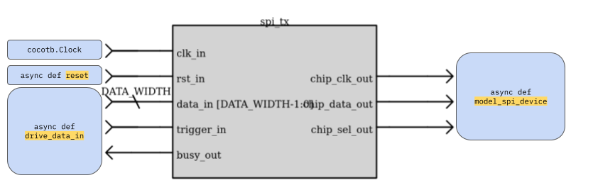
Now, let's dive into a slightly more complicated function: a coroutine that can continually emulate the behavior of the device we would connect as a peripheral to our SPI tx module. Lay out a function with the signature:
async def model_spi_device(dut,received_messages):
Within this function, we'll use the signals on chip_sel_out, chip_data_out (aka MOSI), and chip_clk_out) to listen for and collect the messages sent on the SPI bus. received_messages will be a list initialized outside our coroutine, as a simple way to pass the resulting messages out of our coroutine! So within a test, a call to this function would look like:
received_messages = []
cocotb.start_soon( model_spi_device(dut,received_messages) )
And as messages finish sending, received_messages will fill up with the messages sent on the MOSI wire.
Build all of the behavior into some kind of a while True: block, so that the device emulator keeps running as messages keep sending over the SPI bus. Within each loop of the while block, you should:
- Wait for the
FallingEdgeofchip_sel_out - Repeatedly wait for
RisingEdges ofchip_clk_out, and sample out data bits, accumulating a message in some variable, for as long aschip_sel_outis still0. - Once
chip_sel_outrises again, append the complete collected message to thereceived_messageslist.
This approximation of an SPI device is enough to interact with the SPI outputs of our spi_tx module, and prove that the data being transmitted is accurate!
Asserting standards for our SPI communication
Beyond just ensuring that the data sent is correct, it's also very valuable to ensure the specifications of the SPI protocol are being properly met while we're still in simulation; cocotb tests let us ensure such things by incorporating assert statements into our testbenches; let's add assertions for a couple components of the SPI protocol.
- DCLK Edge Count
For each time that
chip_sel_outgets held low, we should see a total ofDATA_WIDTH(the parameter from our dut) clock periods pass onchip_clk_out! If there are fewer or more than this, then our transmitter may be making errors regarding the holding of CS (or some number of other issues!)
In order to check for this, add to your model_spi_device() function: create a count variable that keeps track of how many rising DCLK edges there are before CS goes high, and assert that it's equal to DATA_WIDTH! Parameters of a module are available in cocotb with the same format as signals: here, dut.DATA_WIDTH.value will get the value you seek.2
- DCLK Proper Period
Based on the
DATA_CLK_PERIODparameter, we should know how exactly many system clock cycles appear within the clock period of DCLK. Put this information to the test! Create a new coroutineasync def assert_spi_clock(dut)to run alongside your other coroutines, that asserts the duration of each DCLK cycle to be the appropriate length. Usingstart_soon()like we did above, you can start this coroutine to ensure the clock periods of your SPI bus are appropriate! We won't lay out the specifics for you for this one, but some tips and edge cases that might be helpful:
- Cocotb has a
get_sim_timefunction to view the current simulation time, which could be useful to store as you compare the current time with the time of the last clock edge. - If the module gets reset, then you may end up with a clock edge that's cut short of what you expect, so it may be wise to only check an assertion if reset isn't high!
- If the module sits idle, then the clock is not running and therefore could end up with a "clock period" that's too long; it may also be wise to discount the first half-period that follows a falling CS edge.
Pulling them all together
With all these helpful functions written, the actual sequence of statements that need to be written into your high-level test hopefully will feel quite a bit simpler! And with that simplicity comes the ability to easily change high-level specifics of the test without worrying that you'll break everything else!
Write one @cocotb.test() to test with sending in a singular test value to drive over spi_tx, and then assert that the value received in received_messages matches the value you expect to go in! The test should be sure to do the following:
- Start a clock running
awaitthe driving of a reset signal- Start your coroutines running: both
model_spi_deviceandassert_spi_clock(using cocotb'sstart_soon) awaitthe driving of a value ontodata_inawaitwhen the module is no longer busy, plus a few extra clock cycles to make sure the module is trully done.assertthe equality between the value passed intodata_inand the data accumulated by `SPI.
Then, write a similar test that tests and checks the values of multiple SPI messages one after the other!
Once you're done with these, start running your tests on your spi_tx module! Look through the waveforms you generate and any print statements or assertion failures you run into, to start debugging both your testbench and your spi_tx module, until you're satisfied with the functionality of your SPI transmitter. Then, marvel in the confidence you've gained by rigorously testing your module :) #10;-based testbenches could never do that for you :)
test_spi_tx.py testbench here!

Optional expansion: SPI MISO
If you'd like to more expansively have a verified full SPI controller at your disposal, consider adding the MISO half of SPI to your model! Here are roughly some steps that could help you with this:
- Add another mutable list to your
model_spi_devicecoroutine, for queuing messages for your model to send on the MISO wire. - Bother your friends in 6.2053 to test on the
spi_conthey just wrote for their lab due this Wednesday, so you can use it to test your testbench!4 They won't have abusy_outsignal on their design, but you can instead roughly interpretCS=0to mean that the spi_controller is busy. They'll have additionaldata_outanddata_valid_outsignals for transmitting the data read in from the MISO wire, which your model will now be generating! Maybe you can have a symbiotic relationship where you help them debug their module while you debug your testbench :) - Write another coroutine to forever-listen to the outputs of the
data_outbus coming out of yourspi_conmodule and collect them into a list, so that you can compare the messages received by the controller to the messages your peripheral is trying to send.
depending on the way you write it, it may also be helpful to you to make a little reverse_bits function to take an integer and return the same bits but reversed as an integer!
spi_tx.sv testbench here!
Footnotes
1Use your references! Remember how Python syntax goes, and poke through the cocotb docs and the cocotb reference card as you write your code.
2 typo corrected 2024-09-18 12pm, this said the wrong param name before
3if you have no such friends, we might be able to give you an implementation to mess with; or you could jump straight to writing your own!
4Maybe if you make a good enough one, we'll turn it into the answer checker for the 6.205 students